Saturday, 4 August 2018

How to Configure High Availability on PAN-OS


How to Configure High Availability on PAN-OS

Prerequisites for Active/Passive HA

To set up high availability on your Palo Alto Networks firewalls, you need a pair of firewalls that meet the following requirements:
  • The same model—Both the firewalls in the pair must be of the same hardware model or virtual machine model.
  • The same PAN-OS version—Both the firewalls should be running the same PAN-OS version and must each be up-to-date on the application, URL, and threat databases.
  • The same multi virtual system capability—Both firewalls must have Multi Virtual System Capability either enabled or not enabled. When enabled, each firewall requires its own multiple virtual systems licenses.
  • The same type of interfaces—Dedicated HA links, or a combination of the management port and in-band ports that are set to interface type HA.
    • Determine the IP address for the HA1 (control) connection between the HA peers. The HA1 IP address for both peers must be on the same subnet if they are directly connected or are connected to the same switch.
      For firewalls without dedicated HA ports, you can use the management port for the control connection. Using the management port provides a direct communication link between the management planes on both firewalls. However, because the management ports will not be directly cabled between the peers, make sure that you have a route that connects these two interfaces across your network.
    • If you use Layer 3 as the transport method for the HA2 (data) connection, determine the IP address for the HA2 link. Use Layer 3 only if the HA2 connection must communicate over a routed network. The IP subnet for the HA2 links must not overlap with that of the HA1 links or with any other subnet assigned to the data ports on the firewall.
  • The same set of licenses—Licenses are unique to each firewall and cannot be shared between the firewalls. Therefore, you must license both firewalls identically. If both firewalls do not have an identical set of licenses, they cannot synchronize configuration information and maintain parity for a seamless failover.


Overview

This document describes how to configure High Availability (HA) on a pair of identical Palo Alto Networks firewalls.
Note: This document does not address configuring HA for PA-200 devices.

Steps

Configure First Device
  1. Go to Network tab > Interfaces.
    ss1.png
    Notes:
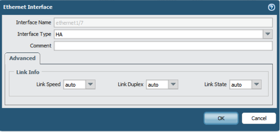
    The HA links should look similar to the following screenshot.
    ss2.png
    1. Confirm the planned HA links are up.
    2. Configure both interfaces to be Interface Type HA.
    • Skip this step if configuring a pair of PA-3000, PA-4000 or PA-5000 Series devices. All other firewalls, including VM-Series, require specific ports to be configured as type HA.
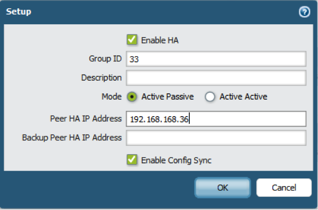
  2. Go to Device tab > HIgh Availability > General.
    ss3.png
    Notes:
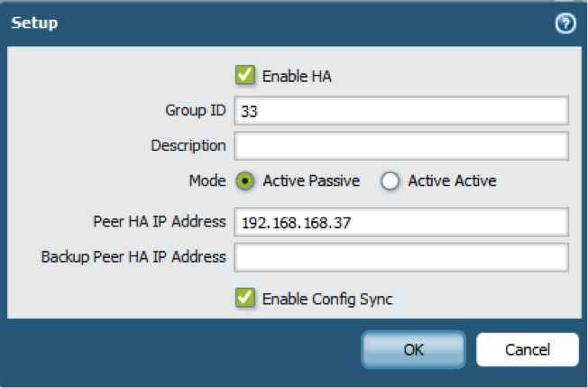
    1. Locate the setup section.
    2. Click on the gear cog to view/edit the settings.
    3. Enable HA.
    4. Enter a group ID that matches both members.
    5. Enter an IP address for the Peer's Control LInk. This will be used in the next step.
    6. Enable Config Sync.
    • The cluster ID is used when creating the virtual MAC for L3 instances. When more than one cluster is on the same L2 network, the ID must be different on each cluster.
    • The Peer HA IP Address (Control Link) can be any IP address that isn't being used currently in the network.
    • It is recommended to add a Backup Peer HA IP Address if there are enough free ports.
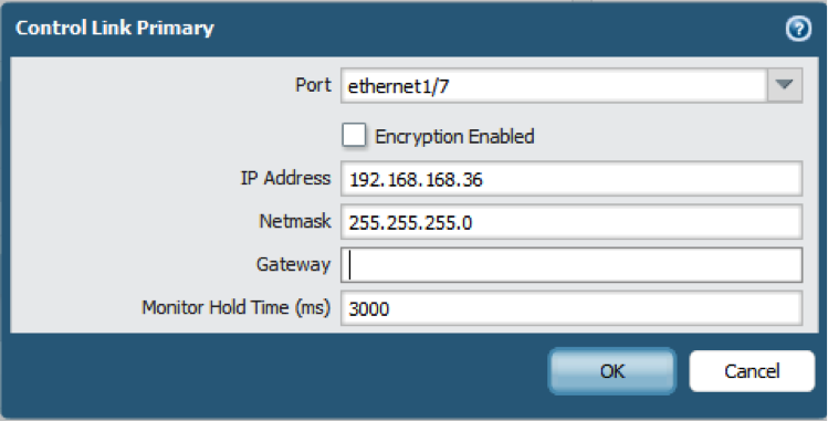
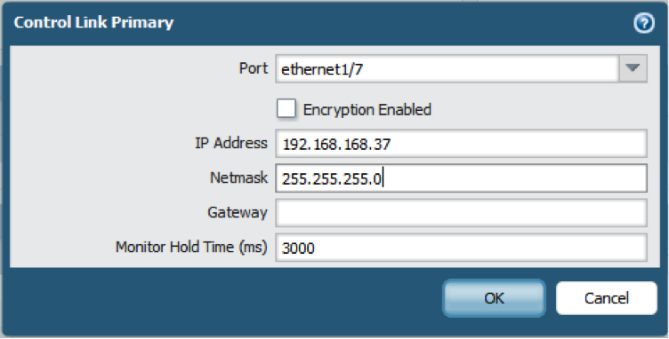
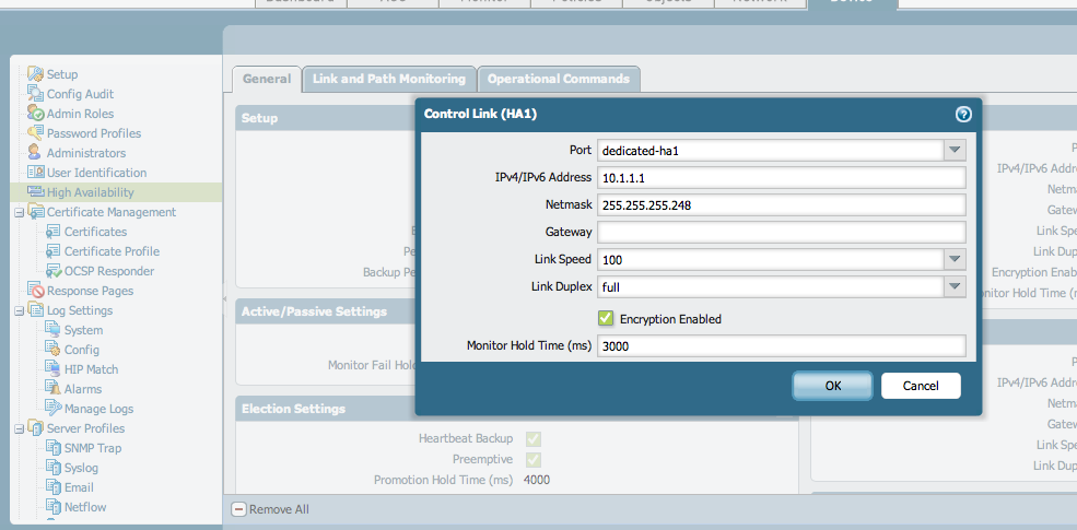
  3. From the General tab, locate the Control Link section and click on Primary.
    ss4.png
    Notes:
    1. Choose the first HA interface to be used for the first device's Control Link.
    2. Ener an IP address that is on the same subnet as the Peer HA IP address, configured in step 2.
    • If the Control Link is not directly connected to the other firewall, you may want to enable encryption (AES-256).
    • If the Control Link IPs are on separate broadcast domains, only the gateway needs to be configured, otherwise it's not needed.
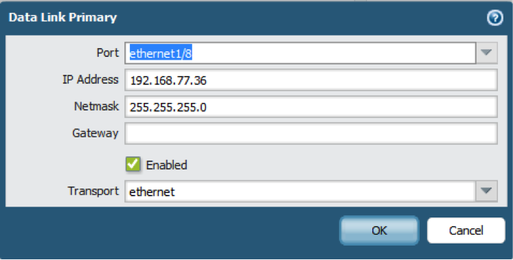
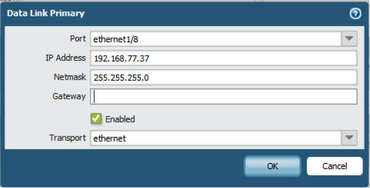
  4. From the General tab, locate the Data Link section and click Primary:
    ss5.png
    Notes: Transport Methods
    1. Choose the other HA interface to be used for the Data Link.
    2. Configure the IP information for the Data Link.
    3. Ensure the Enabled box is checked.
    • Ethernet: Use when the firewalls are connected back-to-back or through a switch (Ethertype 0x7261).
    • IP: Use when Layer 3 transport is required (IP protocol number 99).
    • UDP: Use to take advantage of the fact the checksum is calculated on the entire packet rather than just the header, as in the IP option (UDP port 29281).
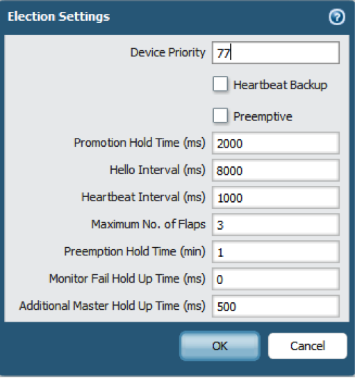
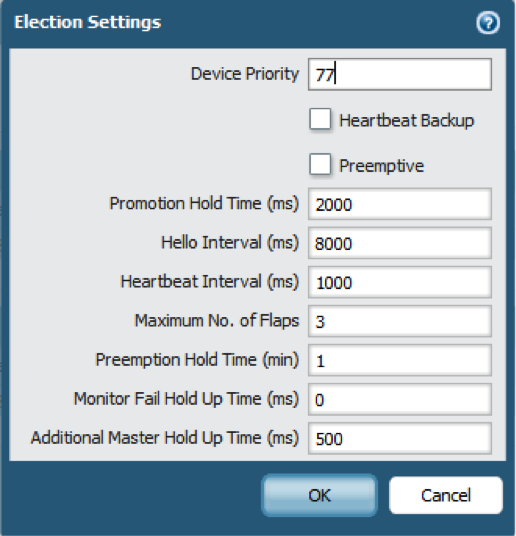
  5. From the General tab, locate the Election Settings section, and click the gear cog:
    ss6.png
    1. To specify one of the firewalls as active, enable Preemptive on both firewalls and set the Device Priority.
      The device with the lowest Device Priority is the active device.
    2. To learn about all of the other settings here, click the ? in the top right corner for detailed explanations.
    3. When state synchronization is enabled; the session table, forwarding table, ARP table, and VPN Security Associations (SAs) are copied from the active device to the passive device over HA2.  When the passive device takes over, existing sessions will continue.
    4. If the devices have IP connectivity between the management IPs, it is recommended to enable the Heartbeat Backup, which send pings over the management interface.
  6. Commit the configuration.
    At this point, any Layer3 interface gets a new (shared) MAC address, and multiple gratuitous ARPs are sent out to each layer3 interface informing the attached switches of the new IP/MAC combination.
    ss7.png
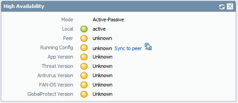
  7. Confirm the HA is active on the local firewall.
    The firewall’s status should show active and the other values should be unknown, as shown below:
    ss8.png
    1. Go to the Dashboard tab.
    2. Add the High Availability widget.
    3. Widgets > System > High Availability.
  8. Configure the Peer Device.
  9. Refer to step 1, ensure the Peer device has two HA links configured to communicate to the first device’s HA links.
    ss9.png
    1. Go to the setup section of the Peer Device and enable HA. Refer to step 2.
    2. Assign the same cluster ID as on the other device.
    3. Enter the IP address assigned to the other firewall’s Control Link.
    4. Enable Config Sync.
  10. From the General tab, locate the Control Link section and click on Primary.
    ss10.png
    Note: If encryption is enabled on the First device, enable it here as well.
    1. Choose the first HA interface to be used for the Second Device’s Control Link.
    2. Enter an IP address that is on the same subnet as the Peer HA IP address configured in Step 8.
  11. From the General tab, locate the Data Link section and click on Primary:
    ss11.png
    1. Choose the other HA interface to be used for the Data Link.
    2. Configure the IP information for the Data Link.
    3. Ensure the Enabled box is checked.
    4. Ensure the Transport drop-down matches the first device’s configuration.
  12. Replicate the settings on the First device with the exception of enabled Preemptive on the First device:
    ss12.png
    For this configuration, Preemptive is off.
    1. Enable Preemptive.
    2. Configure the priority field. A higher number means lower priority.
  13. Commit the changes on the Second device:
    ss13.png
  14. Go to the first device.
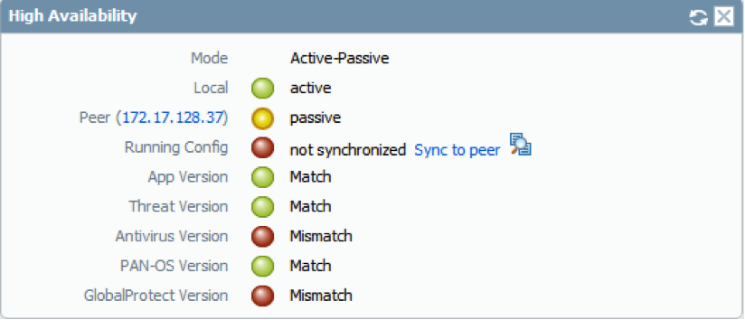
    ss14.png
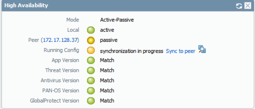
    1. Ensure it still shows as active and it sees the peer device as passive.
    2. Ensure all dynamic updates are synced.
    3. In this example Antivirus and GlobalProtect are not synced.
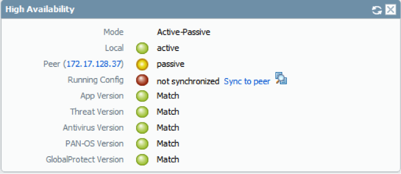
  15. Update as needed so everything matches, as shown below:
    ss15.png
  16. Once everything matches on both devices, go to the active member's Dashboard tab and click Sync to peer. It should say synchronization in progress.
    ss16.png
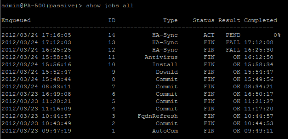
  17. Go to the second (passive) device's CLI and check the HA sync process by running:
    > show jobs all
    The first two attempts failed. Determine and fix the cause of the failure.
    ss17.png
  18. To get more details on the failed job, run:
    > show jobs id <id number of the HA-Sync job>
    The first sync failure is ID 13.
    ss18.png
    There is a security rule on the passive device named “Samir” that’s causing the HA-Sync process to fail. The rule is a shared rule from a previous Panorama configuration.
    Delete the rule and run the Sync to peer again from the Active Device’s Dashboard tab. The job finished successfully this time:
    ss19.png
    High Availability is configured.
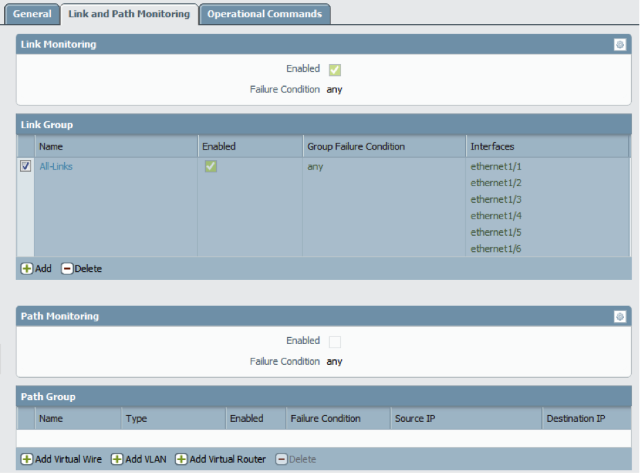
  19. Configure Link Monitoring and Path Monitoring (optional):
    ss20.png
    1. Device tab > High Availability > Link and Path Monitoring tab.
    2. In this example, monitoring all links. This means, if any link state goes down on the active device a failover occurs.
    3. In this example, Path Monitoring is not configured.
    4. Click the “?” button, in the top right corner of the Link and Path Monitoring tab, to read about Link Monitoring and Path Monitoring.

owner: jseals


How to enable encryption on HA1 in high availability configurations

by rvanderveken on ‎03-29-2013 01:48 AM - edited on ‎06-13-2016 11:26 AM by (7,306 Views)

Configuration

  • ,

High Availability

  • ,

Management

Overview

This document describes how to enable encryption on HA1 traffic between two Palo Alto Networks firewalls.

Steps

Every Palo Alto Networks firewall has its own high-availability-key that can be used to encrypt HA1 traffic. Before the encryption can be enabled, the key needs to be exported from PA1 and imported into PA2. The PA2 key also needs to be exported and imported into PA1. After the keys are imported, the final step is to have each firewall explicitly accept its peer's DSA key. This operation can only be done via the CLI.

  1. Export key on PA1.
    From the CLI:
    > scp export high-availability-key from HA-key-0009C100762 to user@server_ip:/directory

    From the GUI:
    original.png
  2. Import key on PA2.
    From CLI:
    > scp import high-availability-key from user@server_ip:/directory/HA-key-0009C100762

    From GUI:
    Screen Shot 2016-02-03 at 9.21.01 am.png 
  3. Repeat steps 1 and 2 above, but export the key from PA2 and import into PA1.
  4. Enable the encryption and perform a commit on both devices.
    Screen Shot 2013-03-29 at 10.04.41.png
  5. To finalize the RSA key exchange between HA nodes, access the CLI from each node and SSH to the peer. When prompted to install the RSA token, type yes.
For example:
1.1.1.1 < HA Peer MGT Interface IP address.
admin@PA-3050> ssh host 1.1.1.1
The authenticity of host '1.1.1.1 (1.1.1.1)' can't be established.
DSA key fingerprint is e9:de:76:fb:db:95:98:7d:c8:45:c4:83:dc:35:f1:2b.
Are you sure you want to continue connecting (yes/no)? yes
Warning: Permanently added '1.1.1.1' (DSA) to the list of known hosts.
admin@1.1.1.1's password:

Additional info


If you have issues with the key or simply want to renew them, use the following CLI command.

Note: Please be aware that this command will cause the firewall to reboot automatically.

> debug system ssh-key-reset high-availability
Executing this command will reset the high-availability SSH keys and reboot the system. Do you want to continue? (y or n)
Broadcast message from root (Fri Mar 29 10:10:28 2013):
The system is going down for reboot NOW

___________________________________________________________________________________________________________________

PALO ALTO CONFIGURE ACTIVE / PASSIVE

Configure Active/Passive HA


Configuration Guidelines for Active/Passive HA

To set up an active (PeerA) passive (PeerB) pair in HA, you must configure some options identically on both firewalls and some independently (non-matching) on each firewall. These HA settings are not synchronized between the firewalls. For details on what is/is not synchronized, see Reference: HA Synchronization .
The following checklist details the settings that you must configure identically on both firewalls:
  • You must enable HA on both firewalls.
  • You must configure the same Group ID value on both firewalls. The firewall uses the Group ID value to create a virtual MAC address for all the configured interfaces. See Floating IP Address and Virtual MAC Address for information about virtual MAC addresses. When a new active firewall takes over, it sends Gratuitous ARP messages from each of its connected interfaces to inform the connected Layer 2 switches of the virtual MAC address’ new location.
  • If you are using in-band ports as HA links, you must set the interfaces for the HA1 and HA2 links to type HA.
  • Set the HA Mode to Active Passive on both firewalls.
  • If required, enable preemption on both firewalls. The device priority value, however, must not be identical.
  • If required, configure encryption on the HA1 link (for communication between the HA peers) on both firewalls.
  • Based on the combination of HA1 and HA1 Backup ports you are using, use the following recommendations to decide whether you should enable heartbeat backup:
    HA functionality (HA1 and HA1 backup) is not supported on the management interface if it's configured for DHCP addressing (IP Type set to DHCP Client), except for AWS.
    • HA1: Dedicated HA1 port
      HA1 Backup: In-band port
      Recommendation: Enable Heartbeat Backup
    • HA1: Dedicated HA1 port
      HA1 Backup: Management port
      Recommendation: Do not enable Heartbeat Backup
    • HA1: In-band port
      HA1 Backup: In-band port
      Recommendation: Enable Heartbeat Backup
    • HA1: Management port
      HA1 Backup: In-band port
      Recommendation: Do not enable Heartbeat Backup
The following table lists the HA settings that you must configure independently on each firewall. See Reference: HA Synchronization for more information about other configuration settings are not automatically synchronized between peers.


Independent Configuration Settings
PeerA
PeerB
Control Link
IP address of the HA1 link configured on this firewall (PeerA).
IP address of the HA1 link configured on this firewall (PeerB).
For firewalls without dedicated HA ports, use the management port IP address for the control link.
Data Link
The data link information is synchronized between the firewalls after HA is enabled and the control link is established between the firewalls.
By default, the HA2 link uses Ethernet/Layer 2.
If using a Layer 3 connection, configure the IP address for the data link on this firewall (PeerA).
By default, the HA2 link uses Ethernet/Layer 2.
If using a Layer 3 connection, configure the IP address for the data link on this firewall (PeerB).
Device Priority (required, if preemption is enabled)
The firewall you plan to make active must have a lower numerical value than its peer. So, if Peer A is to function as the active firewall, keep the default value of 100 and increment the value on PeerB.
If the firewalls have the same device priority value, they use the MAC address of their HA1 as the tie-breaker.
If PeerB is passive, set the device priority value to a number larger than the setting on PeerA. For example, set the value to 110.
Link Monitoring—Monitor one or more physical interfaces that handle vital traffic on this firewall and define the failure condition.
Select the physical interfaces on the firewall that you would like to monitor and define the failure condition (all or any) to trigger a failover.
Pick a similar set of physical interfaces that you would like to monitor on this firewall and define the failure condition (all or any) to trigger a failover.
Path Monitoring—Monitor one or more destination IP addresses that the firewall can use ICMP pings to ascertain responsiveness.
Define the failure condition (all or any), ping interval and the ping count. This is particularly useful for monitoring the availability of other interconnected networking devices. For example, monitor the availability of a router that connects to a server, connectivity to the server itself, or some other vital device that is in the flow of traffic.
Make sure that the node/device that you are monitoring is not likely to be unresponsive, especially when it comes under load, as this could cause a a path monitoring failure and trigger a failover.
Pick a similar set of devices or destination IP addresses that can be monitored for determining the failover trigger for PeerB. Define the failure condition (all or any), ping interval and the ping count.

CONFIGURATION OF PALO ALTO ACTIVE TO PASSIVE 


The following procedure shows how to configure a pair of firewalls in an active/passive deployment as depicted in the following example topology.
HA_topology.png
To configure an active/passive HA pair, first complete the following workflow on the first firewall and then repeat the steps on the second firewall.
  1. Connect the HA ports to set up a physical connection between the firewalls.
    • For firewalls with dedicated HA ports, use an Ethernet cable to connect the dedicated HA1 ports and the HA2 ports on peers. Use a crossover cable if the peers are directly connected to each other.
    • For firewalls without dedicated HA ports, select two data interfaces for the HA2 link and the backup HA1 link. Then, use an Ethernet cable to connect these in-band HA interfaces across both firewalls.
    Use the management port for the HA1 link and ensure that the management ports can connect to each other across your network.
  2. Enable ping on the management port.
    Enabling ping allows the management port to exchange heartbeat backup information.
    1. Select DeviceSetupManagement and edit the Management Interface Settings.
    2. Select Ping as a service that is permitted on the interface.
  3. If the firewall does not have dedicated HA ports, set up the data ports to function as HA ports.
    For firewalls with dedicated HA ports continue to the next step.
    1. Select NetworkInterfaces.
    2. Confirm that the link is up on the ports that you want to use.
    3. Select the interface and set Interface Type to HA.
    4. Set the Link Speed and Link Duplex settings, as appropriate.
  4. Set the HA mode and group ID.
    1. Select DeviceHigh AvailabilityGeneral and edit the Setup section.
    2. Set a Group ID and optionally a Description for the pair. The Group ID uniquely identifies each HA pair on your network. If you have multiple HA pairs that share the same broadcast domain you must set a unique Group ID for each pair.
    3. Set the mode to Active Passive.
  5. Set up the control link connection.
    This example shows an in-band port that is set to interface type HA.
    For firewalls that use the management port as the control link, the IP address information is automatically pre-populated.
    1. In DeviceHigh AvailabilityGeneral, edit the Control Link (HA1) section.
    2. Select the Port that you have cabled for use as the HA1 link.
    3. Set the IPv4/IPv6 Address and Netmask.
      If the HA1 interfaces are on separate subnets, enter the IP address of the Gateway. Do not add a gateway address if the firewalls are directly connected
  6. (Optional) Enable encryption for the control link connection.
    This is typically used to secure the link if the two firewalls are not directly connected, that is if the ports are connected to a switch or a router.
    1. Export the HA key from one firewall and import it into the peer firewall.
      1. Select DeviceCertificate ManagementCertificates.
      2. Select Export HA key. Save the HA key to a network location that the peer can access.
      3. On the peer firewall, select DeviceCertificate ManagementCertificates, and select Import HA key to browse to the location that you saved the key and import it in to the peer.
    2. Select DeviceHigh AvailabilityGeneral, edit the Control Link (HA1) section.
    3. Select Encryption Enabled.
  7. Set up the backup control link connection.
    1. In DeviceHigh AvailabilityGeneral, edit the Control Link (HA1 Backup) section.
    2. Select the HA1 backup interface and set the IPv4/IPv6 Address and Netmask.
  8. Set up the data link connection (HA2) and the backup HA2 connection between the firewalls.
    1. In DeviceHigh AvailabilityGeneral, edit the Data Link (HA2) section.
    2. Select the Port to use for the data link connection.
    3. Select the Transport method. The default is ethernet, and will work when the HA pair is connected directly or through a switch. If you need to route the data link traffic through the network, select IP or UDP as the transport mode.
    4. If you use IP or UDP as the transport method, enter the IPv4/IPv6 Address and Netmask.
    5. Verify that Enable Session Synchronization is selected.
    6. Select HA2 Keep-alive to enable monitoring on the HA2 data link between the HA peers. If a failure occurs based on the threshold that is set (default is 10000 ms), the defined action will occur. For active/passive configuration, a critical system log message is generated when an HA2 keep-alive failure occurs.
      You can configure the HA2 keep-alive option on both firewalls, or just one firewall in the HA pair. If the option is only enabled on one firewall, only that firewall will send the keep-alive messages. The other firewall will be notified if a failure occurs.
    7. Edit the Data Link (HA2 Backup) section, select the interface, and add the IPv4/IPv6 Addressand Netmask.
  9. Enable heartbeat backup if your control link uses a dedicated HA port or an in-band port.
    You do not need to enable heartbeat backup if you are using the management port for the control link.
    1. In DeviceHigh AvailabilityGeneral, edit the Election Settings.
    2. Select Heartbeat Backup.
      To allow the heartbeats to be transmitted between the firewalls, you must verify that the management port across both peers can route to each other.
      Enabling heartbeat backup also allows you to prevent a split-brain situation. Split brain occurs when the HA1 link goes down causing the firewall to miss heartbeats, although the firewall is still functioning. In such a situation, each peer believes that the other is down and attempts to start services that are running, thereby causing a split brain. When the heartbeat backup link is enabled, split brain is prevented because redundant heartbeats and hello messages are transmitted over the management port.
  10. Set the device priority and enable preemption.
    This setting is only required if you wish to make sure that a specific firewall is the preferred active firewall. For information, see Device Priority and Preemption .
    1. In DeviceHigh AvailabilityGeneral, edit the Election Settings.
    2. Set the numerical value in Device Priority. Make sure to set a lower numerical value on the firewall that you want to assign a higher priority to.
      If both firewalls have the same device priority value, the firewall with the lowest MAC address on the HA1 control link will become the active firewall.
    3. Select Preemptive.
      You must enable preemptive on both the active firewall and the passive firewall.
  11. (Optional) Modify the HA Timers .
    By default, the HA timer profile is set to the Recommended profile and is suited for most HA deployments.
    1. In DeviceHigh AvailabilityGeneral, edit the Election Settings.
    2. Select the Aggressive profile for triggering failover faster; select Advanced to define custom values for triggering failover in your set up.
      To view the preset value for an individual timer included in a profile, select Advanced and click Load Recommended or Load Aggressive. The preset values for your hardware model will be displayed on screen.
  12. (Optional), only configured on the passive firewall) Modify the link status of the HA ports on the passive firewall.
    The passive link state is shutdown, by default. After you enable HA, the link state for the HA ports on the active firewall will be green and those on the passive firewall will be down and display as red.
    Setting the link state to Auto allows for reducing the amount of time it takes for the passive firewall to take over when a failover occurs and it allows you to monitor the link state.
    To enable the link status on the passive firewall to stay up and reflect the cabling status on the physical interface:
    1. In DeviceHigh AvailabilityGeneral, edit the Active Passive Settings.
    2. Set the Passive Link State to Auto.
      The auto option decreases the amount of time it takes for the passive firewall to take over when a failover occurs.
      Although the interface displays green (as cabled and up) it continues to discard all traffic until a failover is triggered.
      When you modify the passive link state, make sure that the adjacent devices do not forward traffic to the passive firewall based only on the link status of the firewall.
  13. Enable HA.
    1. Select DeviceHigh AvailabilityGeneral and edit the Setup section.
    2. Select Enable HA.
    3. Select Enable Config Sync. This setting enables the synchronization of the configuration settings between the active and the passive firewall.
    4. Enter the IP address assigned to the control link of the peer in Peer HA1 IP Address.
      For firewalls without dedicated HA ports, if the peer uses the management port for the HA1 link, enter the management port IP address of the peer.
    5. Enter the Backup HA1 IP Address.
  14. (Optional) Enable LACP and LLDP Pre-Negotiation for Active/Passive HA for faster failover if your network uses LACP or LLDP.
    Enable LACP and LLDP before configuring HA pre-negotiation for the protocol if you want pre-negotiation to function in active mode.
    1. Ensure that in Step 12 you set the link state to Auto.
    2. Select NetworkInterfacesEthernet.
    3. To enable LACP active pre-negotiation:
      1. Select an AE interface in a Layer 2 or Layer 3 deployment.
      2. Select the LACP tab.
      3. Select Enable in HA Passive State.
      4. Click OK.
        You cannot also select Same System MAC Address for Active-Passive HAbecause pre-negotiation requires unique interface MAC addresses on the active and passive firewalls.
    4. To enable LACP passive pre-negotiation:
      1. Select an Ethernet interface in a virtual wire deployment.
      2. Select the Advanced tab.
      3. Select the LACP tab.
      4. Select Enable in HA Passive State.
      5. Click OK.
    5. To enable LLDP active pre-negotiation:
      1. Select an Ethernet interface in a Layer 2, Layer 3, or virtual wire deployment.
      2. Select the Advanced tab.
      3. Select the LLDP tab.
      4. Select Enable in HA Passive State.
      5. Click OK.
        If you want to allow LLDP passive pre-negotiation for a virtual wire deployment, perform Step e but do not enable LLDP itself.
  15. Save your configuration changes.
    Click Commit.
  16. After you finish configuring both firewalls, verify that the firewalls are paired in active/passive HA.
    1. Access the Dashboard on both firewalls, and view the High Availability widget.
    2. On the active firewall, click the Sync to peer link.
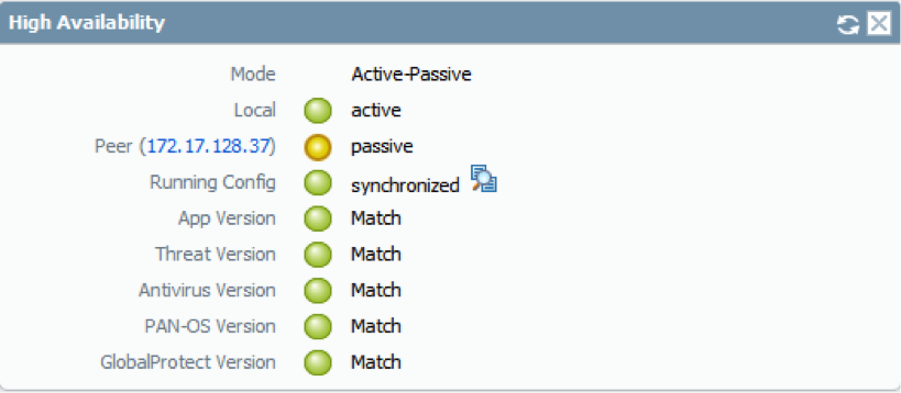
    3. Confirm that the firewalls are paired and synced, as shown as follows:
      • On the passive firewall: the state of the local firewall should display passive and the Running Config should show as synchronized.
      • On the active firewall: The state of the local firewall should display active and the Running Config should show as synchronized.

      _____________________________________________________

Define HA Failover Conditions


  • To configure link monitoring, define the interfaces you want to monitor. A change in the link state of these interfaces will trigger a failover.
    1. Select DeviceHigh AvailabilityLink and Path Monitoring and Add a Link Group.
    2. Name the Link GroupAdd the interfaces to monitor, and select the Failure Condition for the group. The Link group you define is added to the Link Group section.
  • (Optional) Modify the failure condition for the Link Groups that you configured (in the preceding step) on the firewall.
    By default, the firewall will trigger a failover when any monitored link fails.
    1. Select the Link Monitoring section.
    2. Set the Failure Condition to All.
      The default setting is Any.
  • To configure path monitoring, define the destination IP addresses that the firewall should ping to verify network connectivity.
    1. In the Path Group section of the DeviceHigh AvailabilityLink and Path Monitoring tab, pick the Add option for your set up: Virtual Wire, VLAN, or Virtual Router.
    2. Select the appropriate item from the drop-down for the Name and Add the IP addresses (source and/or destination, as prompted) that you wish to monitor. Then select the Failure Condition for the group. The path group you define is added to the Path Group section.
  • (Optional) Modify the failure condition for all Path Groups configured on the firewall.
    By default, the firewall will trigger a failover when any monitored path fails.
    Set the Failure Condition to All.
    The default setting is Any.
  • Commit the configuration.
  • Verify Failover

    To test that your HA configuration works properly, trigger a manual failover and verify that the firewalls transition states successfully.
    1. Suspend the active firewall.
      Select DeviceHigh AvailabilityOperational Commands and click the Suspend local device link.
    2. Verify that the passive firewall has taken over as active.
      On the Dashboard, verify that the state of the passive firewall changes to active in the High Availability widget.
    3. Restore the suspended firewall to a functional state. Wait for a couple of minutes, and then verify that preemption has occurred, if Preemptive is enabled.
      1. On the firewall you previously suspended, select DeviceHigh AvailabilityOperational Commands and click the Make local device functional link.
      2. In the High Availability widget on the Dashboard, confirm that the firewall has taken over as the active firewall and that the peer is now in a passive state.
    4. ______________________________________________________________________________________________

    Configure Active/Active HA PALO ALTO


    Configure Active/Active HA

    The following procedure describes the basic workflow for configuring your firewalls in an active/active configuration. However, before you begin, Determine Your Active/Active Use Case for configuration examples more tailored to your specific network environment.
    To configure active/active, first complete the following steps on one peer and then complete them on the second peer, ensuring that you set the Device ID to different values (0 or 1) on each peer.
    1. Connect the HA ports to set up a physical connection between the firewalls.
      For each use case, the firewalls could be any hardware model; choose the HA3 step that corresponds with your model.
      • For firewalls with dedicated HA ports, use an Ethernet cable to connect the dedicated HA1 ports and the HA2 ports on peers. Use a crossover cable if the peers are directly connected to each other.
      • For firewalls without dedicated HA ports, select two data interfaces for the HA2 link and the backup HA1 link. Then, use an Ethernet cable to connect these in-band HA interfaces across both firewalls. Use the management port for the HA1 link and ensure that the management ports can connect to each other across your network.
      • For HA3:
        • On PA-7000 Series firewalls, connect the High Speed Chassis Interconnect (HSCI-A) on the first chassis to the HSCI-A on the second chassis, and the HSCI-B on the first chassis to the HSCI-B on the second chassis. On a PA-5200 Series firewall (which has one HSCI port), connect the HSCI port on the first chassis to the HSCI port on the second chassis. You can also use data ports for HA3 on PA-5200 Series firewalls.
        • On any other hardware model, use dataplane interfaces for HA3.
    2. Enable ping on the management port.
      Enabling ping allows the management port to exchange heartbeat backup information.
      1. In DeviceSetupManagement, edit Management Interface Settings.
      2. Select Ping as a service that is permitted on the interface.
    3. If the firewall does not have dedicated HA ports, set up the data ports to function as HA ports.
      For firewalls with dedicated HA ports continue to the next step.
      1. Select NetworkInterfaces.
      2. Confirm that the link is up on the ports that you want to use.
      3. Select the interface and set Interface Type to HA.
      4. Set the Link Speed and Link Duplex settings, as appropriate.
    4. Enable active/active HA and set the group ID.
      1. In DeviceHigh AvailabilityGeneral, edit Setup.
      2. Select Enable HA.
      3. Enter a Group ID, which must be the same for both firewalls. The firewall uses the Group ID to calculate the virtual MAC address (range is 1-63).
      4. (Optional) Enter a Description.
      5. For Mode, select Active Active.
    5. Set the Device ID, enable synchronization, and identify the control link on the peer firewall
      1. In DeviceHigh AvailabilityGeneral, edit Setup.
      2. Select Device ID as follows:
        • When configuring the first peer, set the Device ID to 0.
        • When configuring the second peer, set the Device ID to 1.
      3. Select Enable Config Sync. This setting is required to synchronize the two firewall configurations (enabled by default).
      4. Enter the Peer HA1 IP Address, which is the IP address of the HA1 control link on the peer firewall.
      5. (Optional) Enter a Backup Peer HA1 IP Address, which is the IP address of the backup control link on the peer firewall.
      6. Click OK.
    6. Determine whether or not the firewall with the lower Device ID preempts the active-primary firewall upon recovery from a failure.
      1. In DeviceHigh AvailabilityGeneral, edit Election Settings.
      2. Select Preemptive to cause the firewall with the lower Device ID to automatically resume active-primary operation after either firewall recovers from a failure. Both firewalls must have Preemptive selected for preemption to occur.
        Leave Preemptive unselected if you want the active-primary role to remain with the current firewall until you manually make the recovered firewall the active-primary firewall.
    7. Enable heartbeat backup if your control link uses a dedicated HA port or an in-band port.
      You need not enable heartbeat backup if you are using the management port for the control link.
      1. In DeviceHigh AvailabilityGeneral, edit Election Settings.
      2. Select Heartbeat Backup.
        To allow the heartbeats to be transmitted between the firewalls, you must verify that the management port across both peers can route to each other.
        Enabling heartbeat backup allows you to prevent a split-brain situation. Split brain occurs when the HA1 link goes down, causing the firewall to miss heartbeats, although the firewall is still functioning. In such a situation, each peer believes the other is down and attempts to start services that are running, thereby causing a split brain. Enabling heartbeat backup prevents split brain because redundant heartbeats and hello messages are transmitted over the management port.
    8. (Optional) Modify the HA Timers .
      By default, the HA timer profile is set to the Recommended profile and is suited for most HA deployments.
      1. In DeviceHigh AvailabilityGeneral, edit Election Settings.
      2. Select Aggressive to trigger faster failover. Select Advanced to define custom values for triggering failover in your setup.
        To view the preset value for an individual timer included in a profile, select Advanced and click Load Recommended or Load Aggressive. The preset values for your hardware model will be displayed on screen.
    9. Set up the control link connection.
      This example uses an in-band port that is set to interface type HA.
      For firewalls that use the management port as the control link, the IP address information is automatically pre-populated.
      1. In DeviceHigh AvailabilityGeneral, edit Control Link (HA1).
      2. Select the Port that you have cabled for use as the HA1 link.
      3. Set the IPv4/IPv6 Address and Netmask.
        If the HA1 interfaces are on separate subnets, enter the IP address of the Gateway. Do not add a gateway address if the firewalls are directly connected.
    10. (Optional) Enable encryption for the control link connection.
      This is typically used to secure the link if the two firewalls are not directly connected, that is if the ports are connected to a switch or a router.
      1. Export the HA key from one firewall and import it into the peer firewall.
        1. Select DeviceCertificate ManagementCertificates.
        2. Select Export HA key. Save the HA key to a network location that the peer can access.
        3. On the peer firewall, select DeviceCertificate ManagementCertificates, and select Import HA key to browse to the location that you saved the key and import it in to the peer.
      2. In DeviceHigh AvailabilityGeneral, edit the Control Link (HA1).
      3. Select Encryption Enabled.
    11. Set up the backup control link connection.
      1. In DeviceHigh AvailabilityGeneral, edit Control Link (HA1 Backup).
      2. Select the HA1 backup interface and set the IPv4/IPv6 Address and Netmask.
    12. Set up the data link connection (HA2) and the backup HA2 connection between the firewalls.
      1. In DeviceHigh AvailabilityGeneral, edit Data Link (HA2).
      2. Select the Port to use for the data link connection.
      3. Select the Transport method. The default is ethernet, and will work when the HA pair is connected directly or through a switch. If you need to route the data link traffic through the network, select IP or UDP as the transport mode.
      4. If you use IP or UDP as the transport method, enter the IPv4/IPv6 Address and Netmask.
      5. Verify that Enable Session Synchronization is selected.
      6. Select HA2 Keep-alive to enable monitoring on the HA2 data link between the HA peers. If a failure occurs based on the threshold that is set (default is 10000 ms), the defined action will occur. For active/passive configuration, a critical system log message is generated when an HA2 keep-alive failure occurs.
        You can configure the HA2 keep-alive option on both firewalls, or just one firewall in the HA pair. If the option is only enabled on one firewall, only that firewall will send the keep-alive messages. The other firewall will be notified if a failure occurs.
      7. Edit the Data Link (HA2 Backup) section, select the interface, and add the IPv4/IPv6 Addressand Netmask.
      8. Click OK.
    13. Configure the HA3 link for packet forwarding.
      1. In DeviceHigh AvailabilityActive/Active Config, edit Packet Forwarding.
      2. For HA3 Interface, select the interface you want to use to forward packets between active/active HA peers. It must be a dedicated interface capable of Layer 2 transport and set to Interface Type HA.
      3. Select VR Sync to force synchronization of all virtual routers configured on the HA peers. Select when the virtual router is not configured for dynamic routing protocols. Both peers must be connected to the same next-hop router through a switched network and must use static routing only.
      4. Select QoS Sync to synchronize the QoS profile selection on all physical interfaces. Select when both peers have similar link speeds and require the same QoS profiles on all physical interfaces. This setting affects the synchronization of QoS settings on the Network tab. QoS policy is synchronized regardless of this setting.
    14. (Optional) Modify the Tentative Hold time.
      1. In DeviceHigh AvailabilityActive/Active Config, edit Packet Forwarding.
      2. For Tentative Hold Time (sec), enter the number of seconds that a firewall stays in Tentativestate after it fails (range is 10-600, default is 60).
    15. Configure Session Owner and Session Setup .
      1. In DeviceHigh AvailabilityActive/Active Config, edit Packet Forwarding.
      2. For Session Owner Selection, select one of the following:
        • First Packet—The firewall that receives the first packet of a new session is the session owner (recommended setting). This setting minimizes traffic across HA3 and load shares traffic across peers.
        • Primary Device—The firewall that is in active-primary state is the session owner.
      3. For Session Setup, select one of the following:
        • IP Modulo— Distributes session setup load based on parity of the source IP address.
        • Primary Device—The active-primary firewall sets up all sessions.
        • First Packet—The firewall that receives the first packet of a new session performs session setup (recommended setting).
          Start with First Packet for Session Owner and Session Setup, and then based on load distribution, you can change to one of the other options.
        • IP Hash—The firewall uses a hash of either the source IP address or a combination of the source and destination IP addresses to distribute session setup responsibilities.
      4. Click OK.
    16. Configure an HA virtual address.
      You need a virtual address to use a Floating IP Address and Virtual MAC Address or ARP Load-Sharing.
      1. In DeviceHigh AvailabilityActive/Active ConfigAdd a Virtual Address.
      2. Enter or select an Interface.
      3. Select the IPv4 or IPv6 tab and click Add.
      4. Enter an IPv4 Address or IPv6 Address.
      5. For Type:
        • Select Floating to configure the virtual IP address to be a floating IP address.
        • Select ARP Load Sharing to configure the virtual IP address to be a shared IP address and skip to Configure ARP Load-Sharing.
    17. Configure the floating IP address.
      1. Do not select Floating IP bound to the Active-Primary device unless you want the active/active HA pair to behave like an active/passive HA pair.
      2. For Device 0 Priority and Device 1 Priority, enter a priority for the firewall configured with Device ID 0 and Device ID 1, respectively. The relative priorities determine which peer owns the floating IP address you just configured (range is 0-255). The firewall with the lowest priority value (highest priority) owns the floating IP address.
      3. Select Failover address if link state is down to cause the firewall to use the failover address when the link state on the interface is down.
      4. Click OK.
    18. Configure ARP Load-Sharing .
      The device selection algorithm determines which HA firewall responds to the ARP requests to provide load sharing.
      1. For Device Selection Algorithm, select one of the following:
        • IP Modulo—The firewall that will respond to ARP requests is based on the parity of the ARP requester's IP address.
        • IP Hash—The firewall that will respond to ARP requests is based on a hash of the ARP requester's IP address.
      2. Click OK.
    19. Enable jumbo frames on firewalls other than PA-7000 Series firewalls.
      Switch ports that connect the HA3 link must support jumbo frames to handle the overhead associated with the MAC-in-MAC encapsulation on the HA3 link.
      The jumbo frame packet size on the firewall must match the setting on the switch.
      1. Select DeviceSetupSession.
      2. In the Session Settings section, select Enable Jumbo Frames.
      3. Click OK.
      4. Repeat on any intermediary networking devices.
    20. Define HA Failover Conditions .
    21. Commit the configuration.
    22. Reboot the firewall after changing the jumbo frame configuration.
      1. Select DeviceSetupOperations.
      2. Click Reboot Device.


    HA Active/Passive Best Practices

    by vbalasubra on ‎01-26-2018 09:39 AM - edited on ‎02-08-2018 01:33 AM by (3,482 Views)

    High Availability

    Connecting HA1 and HA2 – A/P

    A_P1.png
    • Use dedicated HA interfaces on the platforms.
    • If the firewalls are in the same site/location. Connect HA1 and HA2 links back to back. This helps in convergence.
    • Always connect backup links for HA1 and HA2
    • HA1 interface should be faster than HA2.
    • Recommend HA Heartbeat backup.


    Configuring HA settings - Passive Link Settings

    A_P2.png
    • Set the Passive link state to "Auto". Auto setting will bring the interfaces on the passive firewall to UP physical state, the interface will not pass any data traffic.  This facilitates faster failover times.


    HA timers

    A_P3.pngA_P3.png
    • It is recommended to start with “Recommended” HA timers setting. If needed go with “Aggressive” setting.


    HA to act on Network Failures – Link and Path Monitoring

    A_P4.png
    • Have both link and path monitoring enabled.
    • Link Monitoring – Monitor all important links for which you need a failover to happen when the link goes down..
    • Path Monitoring - Monitor more than one path (prefix). Just do not depend on one path.

    Networking– Best Practices

    A_P5.png
    • Graceful Restart (GR) is enabled by default on BGP and OSPF. GR functionality should be enabled on the neighboring routers as well for it to work.
    • GR helps maintain the forwarding tables during switchover and does not flush them out. This is a way faster mechanism than depending on the routing protocol to converge.
    • If Aggregate Ethernet interfaces (Port Channels) with LACP are used then enable LACP pre-negotiation feature to speed up convergence + passive link state to auto.
    • The LACP pre-negotiation feature helps by sending LACP messages out on the passive FW port channel and bring the AE link up beforehand to help in fast failover.


    No comments:

    Post a Comment