TCP/IP suite of protocols
https://docs.google.com/document/d/e/2PACX-1vQFUJBg6ya1v3_727YG6OkzW_2Ui_b5CdT0oSgYrLXh36e5f1ORTMANoS9S_LBhMfi-1PXQmgTCwNxE/pub
The TCP/IP suite is a set of protocols used on computer networks today (most notably on the Internet). It provides an end-to-end connectivity by specifying how data should be packetized, addressed, transmitted, routed and received on a TCP/IP network. This functionality is organized into four abstraction layers and each protocol in the suite resides in a particular layer.
The TCP/IP suite is named after its most important protocols, the Transmission Control Protocol (TCP) and the Internet Protocol (IP). Some of the protocols included in the TCP/IP suite are:


-
ARP (Address Resolution Protocol) – used to convert an IP address to a MAC address.
-
IP (Internet Protocol) – used to deliver packets from the source host to the destination host based on the IP addresses.
-
ICMP (Internet Control Message Protocol) – used to detects and reports network error conditions. Used in ping.
-
TCP (Transmission Control Protocol) – a connection-oriented protocol that enables reliable data transfer between two computers.
-
UDP (User Datagram Protocol) – a connectionless protocol for data transfer. Since a session is not created before the data transfer, there is no guarantee of data delivery.
-
FTP (File Transfer Protocol) – used for file transfers from one host to another.
-
Telnet (Telecommunications Network) – used to connect and issue commands on a remote computer.
-
DNS (Domain Name System) – used for host names to the IP address resolution.
-
HTTP (Hypertext Transfer Protocol) – used to transfer files (text, graphic images, sound, video, and other multimedia files) on the World Wide Web.
The TCP/IP suite is a set of protocols used on computer networks today (most notably on the Internet). It provides an end-to-end connectivity by specifying how data should be packetized, addressed, transmitted, routed and received on a TCP/IP network. This functionality is organized into four abstraction layers and each protocol in the suite resides in a particular layer.
ARP (Address Resolution Protocol) – used to convert an IP address to a MAC address.
IP (Internet Protocol) – used to deliver packets from the source host to the destination host based on the IP addresses.
ICMP (Internet Control Message Protocol) – used to detects and reports network error conditions. Used in ping.
TCP (Transmission Control Protocol) – a connection-oriented protocol that enables reliable data transfer between two computers.
UDP (User Datagram Protocol) – a connectionless protocol for data transfer. Since a session is not created before the data transfer, there is no guarantee of data delivery.
FTP (File Transfer Protocol) – used for file transfers from one host to another.
Telnet (Telecommunications Network) – used to connect and issue commands on a remote computer.
DNS (Domain Name System) – used for host names to the IP address resolution.
HTTP (Hypertext Transfer Protocol) – used to transfer files (text, graphic images, sound, video, and other multimedia files) on the World Wide Web.
TCP/IP, Transmission Control Protocol/Internet Protocol, is the suite of two protocols, TCP and IP, used to interconnect network devices on the Internet. The TCP performs the handshake between the network devices to establish a socket. The socket remains open during the communication. The source TCP converts the data into packets and sends to the destination TCP. The TCP performs acknowledgment for the successful delivery of the packets. If a packet drops on the way, the source TCP resends the packet. The IP layer is responsible for sending and receiving the data to the correct destination. The TCP/IP stack
 is comprised of the following layers.


Layer 1. Physical Layer
The first layer of the seven layers of Open Systems Interconnection (OSI) network model is called the Physical layer. Physical circuits are created on the physical layer of Open Systems Interconnection (OSI) model. Physical layers describe the electrical or optical signals used for communication. Physical layer of the Open Systems Interconnection (OSI) model is only concerned with the physical characteristics of electrical or optical signaling techniques which includes the voltage of the electrical current used to transport the signal, the media type (Twisted Pair, Coaxial Cable, Optical Fiber etc), impedance characteristics, physical shape of the connector, Synchronization etc. The Physical Layer is limited to the processes needed to place the communication signals over the media, and to receive signals coming from that media. The lower boundary of the physical layer of the Open Systems Interconnection (OSI) model is the physical connector attached to the transmission media. Physical layer of the Open Systems Interconnection (OSI) model does not include the transmission media. Transmission media stays outside the scope of the Physical Layer and are also referred to as Layer 0 of the Open Systems Interconnection (OSI) Model.
Layer 2. Datalink Layer
The second layer of the seven layers of Open Systems Interconnection (OSI) network model is called the Datalink layer. The Data Link layer resides above the Physical layer and below the Network layer. Datalink layer is responsible for providing end-to-end validity of the data being transmitted. The Data Link Layer is logically divided into two sublayers, The Media Access Control (MAC) Sublayer and the Logical Link Control (LLC) Sublayer.
Media Access Control (MAC) Sublayer determines the physical addressing of the hosts. The MAC sub-layer maintains MAC addresses (physical device addresses) for communicating with other devices on the network. MAC addresses are burned into the network cards and constitute the low-level address used to determine the source and destination of network traffic. MAC Addresses are also known as Physical addresses, Layer 2 addresses, or Hardware addresses.
The Logical Link Control sublayer is responsible for synchronizing frames, error checking, and flow control.
Layer 3. Network Layer
The third layer of the seven layers of Open Systems Interconnection (OSI) network model is the Network layer. The Network layer of the OSI model is responsible for managing logical addressing information in the packets and the delivery of those packets to the correct destination. Routers, which are special computers used to build the network, direct the data packet generated by Network Layer using information stored in a table known as routing table. The routing table is a list of available destinations that are stored in memory on the routers. The network layer is responsible for working with logical addresses. The logical addresses are used to uniquely identify a computer on the network, but at the same time identify the network that system resides on. The logical address is used by network layer protocols to deliver the packets to the correct network. The Logical addressing system used in Network Layer is known as IP address.
Layer 4. Transport Layer
The fourth layer of the seven layers of Open Systems Interconnection (OSI) network mode is the Transport layer. The Transport layer handles transport functions such as reliable or unreliable delivery of the data to the destination. On the sending computer, the transport layer is responsible for breaking the data into smaller packets, so that if any packet is lost during transmission, the missing packets will be sent again. Missing packets are determined by acknowledgments (ACKs) from the remote device, when the remote device receives the packets. At the receiving system, the transport layer will be responsible for opening all of the packets and reconstructing the original message.
Another function of the transport layer is TCP segment sequencing. Sequencing is a connection-oriented service that takes TCP segments that are received out of order and place them in the right order.
The transport layer also enables the option of specifying a "service address" for the services or application on the source and the destination computer to specify what application the request came from and what application the request is going to.
Many network applications can run on a computer simultaneously and there should be some mechanism to identify which application should receive the incoming data. To make this work correctly, incoming data from different applications are multiplexed at the Transport layer and sent to the bottom layers. On the other side of the communication, the data received from the bottom layers are de-multiplexed at the Transport layer and delivered to the correct application. This is achieved by using "Port Numbers".
The protocols operating at the Transport Layer, TCP (Transmission Control Protocol) and UDP (User Datagram Protocol) uses a mechanism known as "Port Number" to enable multiplexing and de-multiplexing. Port numbers identify the originating network application on the source computer and destination network application on the receiving computer.
Layer 5. Session Layer
The position of Session Layer of the Seven Layered Open Systems Interconnection (OSI) model is between Transport Layer and the Presentation Layer. Session layer is the fifth layer of seven layered Open Systems Interconnection (OSI) Model. The session layer is responsible for establishing, managing, and terminating connections between applications at each end of the communication.
In the connection establishment phase, the service and the rules (who transmits and when, how much data can be sent at a time etc.) for communication between the two devices are proposed. The participating devices must agree on the rules. Once the rules are established, the data transfer phase begins. Connection termination occurs when the session is complete, and communication ends gracefully.
In practice, Session Layer is often combined with the Transport Layer.
Layer 6. Presentation Layer
The position of Presentation Layer in seven layered Open Systems Interconnection (OSI) model is just below the Application Layer. When the presentation layer receives data from the application layer, to be sent over the network, it makes sure that the data is in the proper format. If it is not, the presentation layer converts the data to the proper format. On the other side of communication, when the presentation layer receives network data from the session layer, it makes sure that the data is in the proper format and once again converts it if it is not.
Formatting functions at the presentation layer may include compression, encryption, and ensuring that the character code set (ASCII, Unicode, EBCDIC (Extended Binary Coded Decimal Interchange Code, which is used in IBM servers) etc) can be interpreted on the other side.
For example, if we select to compress the data from a network application that we are using, the Application Layer will pass that request to the Presentation Layer, but it will be the Presentation Layer that does the compression.
Layer 7. Application Layer
The Application Layer the seventh layer in OSI network model. Application Layer is the top-most layer of the seven layered Open Systems Interconnection (OSI) network model. Real traffic data will be often generated from the Application Layer. This may be a web request generated from HTTP protocol, a command from telnet protocol, a file download request from FTP protocol etc.
In this lesson (Seven Layers of Open Systems Interconnection (OSI) Model), you have learned what are the Seven Layers of Open Systems Interconnection (OSI) Model and the functions of these seven layers. The top-most layer of the Seven Layers of Open Systems Interconnection (OSI) Model is the Application Layer and the bottom-most layer of the Seven Layers of Open Systems Interconnection (OSI) Model is Physical Layer. Click "Next" to Continue.
TCP/IP PROTOCOL SUITE
Communications between computers on a network is done through protocol suits. The most widely used and most widely available protocol suite is TCP/IP protocol suite. A protocol suit consists of a layered architecture where each layer depicts some functionality which can be carried out by a protocol. Each layer usually has more than one protocol options to carry out the responsibility that the layer adheres to. TCP/IP is normally considered to be a 4 layer system. The 4 layers are as follows :
-
Application layer
-
Transport layer
-
Network layer
-
Data link layer
Application layer
Transport layer
Network layer
Data link layer
Layer 4. Application Layer
Application layer is the top most layer of four layer TCP/IP model. Application layer is present on the top of the Transport layer. Application layer defines TCP/IP application protocols and how host programs interface with Transport layer services to use the network.
Application layer includes all the higher-level protocols like DNS (Domain Naming System), HTTP (Hypertext Transfer Protocol), Telnet, SSH, FTP (File Transfer Protocol), TFTP (Trivial File Transfer Protocol), SNMP (Simple Network Management Protocol), SMTP (Simple Mail Transfer Protocol) , DHCP (Dynamic Host Configuration Protocol), X Windows, RDP (Remote Desktop Protocol) etc.
Layer 3. Transport Layer
Transport Layer is the third layer of the four layer TCP/IP model. The position of the Transport layer is between Application layer and Internet layer. The purpose of Transport layer is to permit devices on the source and destination hosts to carry on a conversation. Transport layerdefines the level of service and status of the connection used when transporting data.
The main protocols included at Transport layer are TCP (Transmission Control Protocol) and UDP (User Datagram Protocol).
Layer 2. Internet Layer
Internet Layer is the second layer of the four layer TCP/IP model. The position of Internet layer is between Network Access Layer and Transport layer. Internet layer pack data into data packets known as IP datagrams, which contain source and destination address (logical address or IP address) information that is used to forward the datagrams between hosts and across networks. The Internet layer is also responsible for routing of IP datagrams.
Packet switching network depends upon a connectionless internetwork layer. This layer is known as Internet layer. Its job is to allow hosts to insert packets into any network and have them to deliver independently to the destination. At the destination side data packets may appear in a different order than they were sent. It is the job of the higher layers to rearrange them in order to deliver them to proper network applications operating at the Application layer.
The main protocols included at Internet layer are IP (Internet Protocol), ICMP (Internet Control Message Protocol), ARP (Address Resolution Protocol), RARP (Reverse Address Resolution Protocol) and IGMP (Internet Group Management Protocol).
Layer 1. Data Link Layer
Network Access Layer is the first layer of the four layer TCP/IP model. Network Access Layer defines details of how data is physically sent through the network, including how bits are electrically or optically signaled by hardware devices that interface directly with a network medium, such as coaxial cable, optical fiber, or twisted pair copper wire.
The protocols included in Network Access Layer are Ethernet, Token Ring, FDDI, X.25, Frame Relay etc.
The most popular LAN architecture among those listed above is Ethernet. Ethernet uses an Access Method called CSMA/CD (Carrier Sense Multiple Access/Collision Detection) to access the media, when Ethernet operates in a shared media. An Access Method determines how a host will place data on the medium.
IN CSMA/CD Access Method, every host has equal access to the medium and can place data on the wire when the wire is free from network traffic. When a host wants to place data on the wire, it will check the wire to find whether another host is already using the medium. If there is traffic already in the medium, the host will wait and if there is no traffic, it will place the data in the medium. But, if two systems place data on the medium at the same instance, they will collide with each other, destroying the data. If the data is destroyed during transmission, the data will need to be retransmitted. After collision, each host will wait for a small interval of time and again the data will be retransmitted.
In this lesson, you have learned about the four layers of TCP/IP model and the comparison between four layered TCP/IP model and seven layered OSI model. Click "Next" to continue.
TCP stands for transport control protocol. It is a connection oriented and reliable protocol and is used for transfer of crucial data. TCP is a connection orientated protocol with built in error recovery and re transmission.
TCP is used by application protocols that need guaranteed message delivery.
HTTP,FTP, SMTP, POP3, IMAP4 and many other common Internet application protocols use TCP.
On the other hand, UDP stands for User Datagram Protocol. It is an unreliable and connection-less protocol which is used for services that require fast transmission of data.
UDP does not correct or recover errors in the message. Any error detection and recovery is the responsibility of the receiving application. Because there is no connection setup, UDP is faster than TCP and results in less network traffic.
In addition it doesn’t consume resources on the receiving machine as it doesn’t hold a connection open.
Utility applications like DNS, DHCP, RIP and others use UDP.
TCP Three-Way Handshake
Definition - What does Three-Way Handshake mean?
A three-way handshake is a method used in a TCP/IP network to create a connection between a local host/client and server. It is a three-step method that requires both the client and server to exchange SYN and ACK (acknowledgment) packets before actual data communication begins.
A three-way handshake is also known as a TCP handshake.
TCP
|
UDP
|
|
Stands for:
|
Transmission Control Protocol
|
User Datagram Protocol or Universal Datagram Protocol
|
Type of Connection:
|
It is a connection oriented protocol
|
It is a connection less protocol
|
Usage:
|
TCP is used in case of applications in which fast transmission of data is not required
|
UDP is preferred in case of the applications which have the priority of sending the data on time and on faster rates
|
Examples:
|
HTTP, FTP, SMTP Telnet etc
|
DNS, DHCP, TFTP, SNMP, RIP, VOIP etc
|
Ordering of data packets:
|
It rearranges data packets in the order specified
|
No inherent ordering, the data packets of same message may be ordered differently
|
Speed of transfer:
|
Comparatively slow
|
Comparatively fast
|
Reliability:
|
Reliable (defines that data will be definitely sent across)
|
Unreliable
|
Data Flow Control:
|
TCP controls the flow of data
|
UDP does not have an option for flow control
|
The Transmission Control Protocol (TCP) is one of the core protocols of the Internet Protocol Suite. It is a reliable stream delivery service that guarantees delivery of a data stream sent from one host to another without duplication or losing data.
File Transfer Protocol (FTP) is a standard network protocol used to transfer files from one host to another host over a TCP-based network, such as the Internet. FTP is built on a client-server architecture and uses separate control and data connections between the client and server. Authentication is accomplished through the use of a clear-text sign-in protocol and is not considered to be secure.
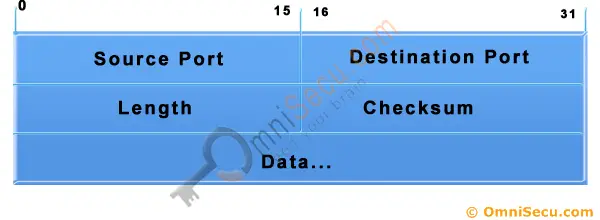
The User Datagram Protocol (UDP) is one of the core members of the Internet Protocol Suite, the set of network protocols used for the Internet. With UDP, computer applications can send messages, in this case referred to as datagrams, to other hosts on an Internet Protocol (IP) network without requiring prior communications to set up special transmission channels or data paths. UDP provides an unreliable service and datagrams may arrive out of order, appear duplicated, or go missing without notice.
DNS
networks communicate with hosts using their IP addresses. It would be very difficult for someone to have to memorize the different IP addresses for the hosts they want to connect to on the network. A Domain Name Service (DNS) makes it easier to identify a host by a domain name. A domain name uses words rather than numbers to identify Internet hosts.
The TCP/IP suite is a collection of internet protocols developed by the Department of Defense. Designed to permit communication among a variety of independent, multivendor systems, support is provided for a wide variety of protocols and services, including TCP, IP, UDP, ARP, and others, on many different types of media. TCP/IP is routable across more than one local area network (LAN). Named for it's two primary protocols, Transmission Control Protocol (TCP) and Internet Protocol (IP), TCP/IP provides end-to-end connectivity specifying how data should be formatted, addressed, transmitted, routed and received at the destination.
The Dynamic Host Configuration Protocol (DHCP) is a network configuration protocol that enables a server on an IP network to automatically assign an IP address to a computer from a predetermined range of numbers. The most essential information needed is an IP address, and a default route and routing prefix. DHCP controls the assignment of unique dynamic IP addresses and routing information, eliminating the manual task by a network administrator.
Trivial File Transfer Protocol (TFTP) is a simple insecure protocol used to transfer files. It is typically implemented on top of the User Datagram Protocol (UDP) using port number 69. Packets are limited to a 512 byte limit and can be easily lost. When a packet smaller than 512 bytes is received, the server assumes the end of the file has been reached and closes the connection. Transmission is not guaranteed to be complete and has no provision for user authentication. TFTP is designed to be small and easy to implement, therefore, lacks most of the features of FTP. TFTP only reads and writes files (or mail) to or from a remote server, it cannot list directories. TFTP can be used for remote booting of devices without hard drives. Used in conjunction with a bootp server, the device receives its addressing information and the address of the TFTP server from which it should boot.
The Domain Name System (DNS) is a hierarchical naming system for computers, services, or any resource connected to the Internet or a private network. Internet and TCP utilities such as telnet, FTP, and SMTP use DNS to translate computer host and domain names to their corresponding IP addresses. DNS allows you to type recognizable names into your Web browser and your computer will automatically find that address on the Internet. Address information is stored in several locations in a hierarchical structure.
Hypertext Transfer Protocol Secure (HTTPS) is a combination of Hypertext Transfer Protocol (HTTP) with SSL/TLS protocol. It provides encrypted communication and secure identification of a network web server. HTTPS connections are often used for payment transactions on the World Wide Web and for sensitive transactions in corporate information systems. HTTPS uses port 443 by default.
Hypertext Transfer Protocol (HTTP) is an application-level protocol used to request and deliver web pages between a server and browser. HTTP is the foundation of data communication for the World Wide Web.
- ARP network layer
Address Resolution Protocol (ARP) is a low-level network protocol used for the resolution of network layer IP addresses into corresponding link layer MAC (Media Access Control) addresses. ARP is the standard of identifying a host's hardware address when only its network IP address is known.
ARP operates at Layer 2 of the OSI model allowing packets or frames on a local network to be delivered to physical (MAC) addresses, not IP addresses. When a machine attempts to communicate with another on the same local network, it will first check it's own ARP cache for the desired IP and MAC addresses. If it doesn't find the desired entry, it will broadcast an ICMP ping request for the IP address to every machine on the local network. If the intended target is online, a reply is returned with the proper IP address and physical address.
ARP operates at Layer 2 of the OSI model allowing packets or frames on a local network to be delivered to physical (MAC) addresses, not IP addresses. When a machine attempts to communicate with another on the same local network, it will first check it's own ARP cache for the desired IP and MAC addresses. If it doesn't find the desired entry, it will broadcast an ICMP ping request for the IP address to every machine on the local network. If the intended target is online, a reply is returned with the proper IP address and physical address.
The Session Initiation Protocol (SIP) is a signaling protocol widely used for controlling communication sessions such as voice and video calls over Internet Protocol (IP). The protocol can be used for creating, modifying and terminating two-party (unicast) or multiparty (multicast) sessions. Sessions may consist of one or several media streams.
The Real-time Transport Protocol (RTP) defines a standardized packet format for delivering audio and video over IP networks. RTP is used extensively in communication and entertainment systems that involve streaming media, such as telephony, video teleconference applications, television services and web-based push-to-talk features.
Secure Shell (SSH) is a cryptographic remote login protocol for secure data communication over an unsecured network. Designed as a replacement for telnet and rlogin, which send information in plaintext, SSH client and server programs provide strong host-to-host and user authentication as well as a number of securely encrypted methods of communication to provide confidentiality and integrity of data. SSH supports data stream compression between the client and the server.
There are two major versions of the SSH protocol in widespread use, SSH v1 and SSH v2. SSH v2 is more secure, and includes SFTP, which is similar to FTP, but is SSH v2 encrypted.
Post Office Protocol (POP3) is a simple, standardized application-layer protocol used for retrieving incoming email from a remote mail server over a TCP/IP connection and saving to a local device. A POP3 server listens on well-known port TCP/110.
The Network Time Protocol (NTP) is a networking protocol and software implementation for synchronizing the clocks of computer systems over packet-switched, variable-latency data networks.
Internet message access protocol (IMAP) is one of the two most prevalent Internet standard protocols for e-mail retrieval, the other being the Post Office Protocol (POP). Virtually all modern e-mail clients and mail servers support both protocols as a means of transferring e-mail messages from a server. IMAP is a client/server protocol in which e-mail is received and held by your Internet server and downloaded from the server by request. Imap permits the manipulation of remote mailboxes as though they were local, and works well with slower modem connections.
Short for Telecommunications network, TELNET is a text based interface protocol that provides an insecure remote access to other computers. Telnet uses a command line interface and can be accessed in Windows from the Start menu by clicking <Start>, <Run>, then by typing: telnet (somesite) 23. Port number 23 is the default port used by telnet, but is usually optional and often not required.
Simple Mail Transfer Protocol (SMTP) is a reliable and efficient mail transport and delivery protocol that is capable of transporting outgoing email across multiple networks. SMTP requires a reliable data stream channel for transmission.
Simple Network Management Protocol (SNMP) is an "Internet-standard protocol for managing devices on IP networks. Devices that typically support SNMP include routers, switches, servers, workstations, printers, modem racks, and more." It is used mostly in network management systems to monitor network-attached devices for conditions that warrant administrative attention.
The Internet Control Message Protocol (ICMP) is one of the core protocols of the Internet Protocol Suite. It is chiefly used by the operating systems of networked computers to send error messages indicating, for example, that a requested service is not available or that a host or router could not be reached. ICMP can also be used to relay query messages.
- IGMP network layer
The Internet Group Management Protocol (IGMP) is a communications protocol used by hosts and adjacent routers on IP networks to establish multicast group memberships.
Transport Layer Security (TLS) is a cryptographic protocol that provides communication security over the Internet. TLS encrypts the segments of network connections above the Transport Layer, using asymmetric cryptography for key exchange, symmetric encryption for privacy, and message authentication codes for message integrity.
TCP IN DEPTH EXPLANATION
QUICK OVERVIEW OF TCP
MAIN FEATURES
Here are the main features of the TCP that we are going to analyse:
- Reliable Transport
- Connection-Oriented
- Flow Control
- Windowing
- Acknowledgements
- More overhead
RELIABLE TRANSPORT
- It's a reliable transport because of the different techniques it uses to ensure that the data received is error free. TCP is a robust protocol used for file transfers where data error is not an option. When you decide to download a 50MB file from a website, you wouldn't want to find out after the download is complete that the file has an error! Even though, in reality, this does happen, it just goes to show that you can't always be perfect with certain things.
- A TCP header within an ethernet II frame

- The TCP individual breakdown of each field within the TCP header along with its length in bits.
- Remember that 8 bits equal to 1 byte.
- The most popular fields within the TCP header are the Source Port, Destination Port and Code bits. These Code bits are also known as 'flags'.
- The rest of the fields help make sure all TCP segments make it to their destination and are reassembled in the correct order, while at the same time providing an error free mechanism should a few segments go missing and never reach their destination.
- Keep in mind that in the pages to follow we will have a detailed look into each available field, for now we are just providing an overview of them
CONNECTION ORIENTED
What this basically means is that a connection is established between the two hosts or rather, the two computers, before any data is transferred. When the term "connection is established" is used, this means that both computers know about each other and have agreed on the exchange of data. This is also where the famous 3-way handshake happens. You will find the SYN and ACK bits in the Code bits field which are used to perform the 3-way handshake. Thanks to the 3-way handshake, TCP is connection oriented.
The following diagram explains the procedure of the 3-way handshake:

STEP 1: Host A sends the initial packet to Host B. This packet has the "SYN" bit enabled. Host B receives the packet and sees the "SYN" bit which has a value of "1" (in binary, this means ON) so it knows that Host A is trying to establish a connection with it.
STEP 2: Assuming Host B has enough resources, it sends a packet back to Host A and with the "SYN and ACK" bits enabled (1). The SYN that Host B sends, at this step, means 'I want to synchronise with you' and the ACK means 'I acknowledge your previous SYN request'.
STEP 3: So... after all that, Host A sends another packet to Host B and with the "ACK" bit set (1), it effectively tells Host B 'Yes, I acknowledge your previous request'.
Once the 3-way handshake is complete, the connection is established (virtual circuit) and the data transfer begins.
FLOW CONTROL
Flow control is used to control the data flow between the connection. If for any reason one of the two hosts are unable to keep up with the data transfer, it is able to send special signals to the other end, asking it to either stop or slow down so it can keep up.
For example, if Host B was a webserver from which people could download games, then obviously Host A is not going to be the only computer downloading from this webserver, so Host B must regulate the data flow to every computer downloading from it. This means it might turn to Host A and tell it to wait for a while until more resources are available because it has another 20 users trying to download at the same time.
Below is a diagram that illustrates a simple flow control session between two hosts. At this point, we only need to understand the concept of flow control:

Generally speaking, when a machine receives a flood of data too quickly for it to process, it stores it in a memory section called a buffer. This buffering action solves the problem only if the data bursts are small and don't last long.
However, if the data burst continues it will eventually exhaust the memory of the receiving end and that will result in the arriving data being discarded. So in this situation the receiving end will simply issue a "Not ready" or "Stop" indicator to the sender, or source of the flood. After the receiver processes the data it has in its memory, it sends out a "Ready" or "Go" transport indicator and the sending machine receives the "Go" indicator and resumes its transmission.
WINDOWING
Because there is time available after the sender transmits the data segment and before it finishes processing acknowledgments from the receiving machine, the sender uses the break to transmit more data. If we wanted to briefly define Windowing we could do so by stating that it is the number of data segments the transmitting machine is allowed to send without receiving an acknowledgment for them.
Windowing controls how much information is transferred from one end to the other. While some protocols quantify information by observing the number of packets, TCP/IP measures it by counting the number of bytes.

Let's explain what is happening in the above diagram.
Host B is sending data to Host A, using a window size equal to one. This means that Host B is expecting an "ACK" for each data segment it sends to Host A. Once the first data segment is sent, Host A receives it and sends an "ACK 2" to Host B. You might be wondering why "ACK 2" and not just "ACK"?
The "ACK 2" is translated by Host B to say: 'I acknowledge (ACK) the packet you just sent me and I am ready to receive the second (2) segment'. So Host B gets the second data segment ready and sends it off to Host A, expecting an "ACK 3" response from Host A so it can send the third data segment for which, as the picture shows, it receives the "ACK 3".
However, if it received an "ACK 2" again, this would mean something went wrong with the previous transmission and Host B will retransmit the lost segment. We will see how this works in the Acknowledgments section later on. Let's now try a different Window size to get a better understanding.. let's say 3!
Keep in mind the way the "ACK's" work, otherwise you might find the following example a bit confusing. If you can't understand it, read the previous example again where the Window size was equal to one.

In the above example, we have a window size equal to 3, which means that Host B can send 3 data segments to Host A before expecting an "ACK" back. Host B sends the first 3 segments (Send 1, Send 2 and Send 3), Host A receives them all in good condition and then sends the "ACK 4" to Host B. This means that Host A acknowledged the 3 data segments Host B sent and awaits the next data segments which, in this case, would be 4, 5 and 6.
ACKNOWLEDGMENTS
Reliable data delivery ensures the integrity of a stream of data sent from one machine to the other through a fully functional data link. This guarantees the data won't be duplicated or lost. The method that achieves this is known as positive acknowledgment with retransmission. This technique requires a receiving machine to communicate with the transmitting source by sending an acknowledgment message back to the sender when it receives data. The sender documents each segment it sends and waits for this acknowledgment before sending the next segment. When it sends a segment, the transmitting machine starts a timer and retransmits if it expires before an acknowledgment is returned from the receiving end.

This figure shows how the Acknowledgments work. If you examine the diagram closely you will see the window size of this transfer which is equal to 3. At first, Host B sends 3 data segments to Host A and they are received in perfect condition so, based on what we learned, Host A sends an "ACK 4" acknowledging the 3 data segments and requesting the next 3 data segments which will be 4, 5, 6. As a result, Host B sends data segments 4, 5, 6 but 5 gets lost somewhere along the way and Host A doesn't receive it so, after a bit of waiting, it realises that 5 got lost and sends an "ACK 5" to Host B, indicating that it would like data segment 5 retransmitted. Now you see why this method is called "positive acknowledgment with retransmission".
At this point Host B sends data segment 5 and waits for Host A to send an "ACK" so it can continue sending the rest of the data. Host A receives the 5th data segment and sends "ACK 7" which means 'I received the previous data segment, now please send me the next 3'. The next step is not shown on the diagram but it would be Host B sending data segments 7, 8 and 9.
Fields in the TCP Header
One of the main protocols in the TCP/IP suite is Transmission Control Protocol (TCP). TCP provides reliable and ordered delivery of data between applications running on hosts on a TCP/IP network. Because of its reliable nature, TCP is used by applications that require high reliability, such as FTP, SSH, SMTP, HTTP, etc.
TCP is connection-oriented, which means that, before data is sent, a connection between two hosts must be established. The process used to establish a TCP connection is known as the three-way handshake. After the connection has been established, the data transfer phase begins. After the data is transmitted, the connection is terminated.
One other notable characteristic of TCP is its reliable delivery. TCP uses sequence numbers to identify the order of the bytes sent from each computer so that the data can be reconstructed in order. If any data is lost during the transmission, the sender can retransmit the data.
Because of all of its characteristics, TCP is considered to be complicated and costly in terms of network usage. The TCP header is up to 24 bytes long and consists of the following fields:
 source port – the port number of the application on the host sending the data.
destination port – the port number of the application on the host receiving the data.
sequence number – used to identify each byte of data.
acknowledgment number – the next sequence number that the receiver is expecting.
header length – the size of the TCP header.
reserved – always set to 0.
flags – used to set up and terminate a session.
window – the window size the sender is willing to accept.
checksum – used for error-checking of the header and data.
urgent – indicates the offset from the current sequence number, where the segment of non-urgent data begins.
options – various TCP options, such as Maximum Segment Size (MSS) or Window Scaling.
NOTE – TCP is a Transport layer protocol (Layer 4 of the OSI model).
destination port – the port number of the application on the host receiving the data.
sequence number – used to identify each byte of data.
acknowledgment number – the next sequence number that the receiver is expecting.
header length – the size of the TCP header.
reserved – always set to 0.
flags – used to set up and terminate a session.
window – the window size the sender is willing to accept.
checksum – used for error-checking of the header and data.
urgent – indicates the offset from the current sequence number, where the segment of non-urgent data begins.
options – various TCP options, such as Maximum Segment Size (MSS) or Window Scaling.
TCP FLAGS
IN-DEPTH TCP HEADER ANALYSIS - INTRODUCTION
:
- Section 1: Source & Destination Port Number
- Section 2: Sequence & Acknowledgement Numbers
- Section 3: Header Length
- Section 4: TCP Flag Options
- Section 5: Window Size, Checksum & Urgent Pointer
- Section 6: TCP Options
- Section 7: TCP Data
Urgent Pointer Flag
The urgent pointer flag is used to identify incoming data as urgent. The incoming segments do not have to wait until the previous segments are consumed by the receiving end but are sent directly and processed immediately. An urgent pointer could be used during a stream of data transfer and stop the data processing on the other end. The abort signal will be sent and queued at the remote machine until all previously sent data is processed. By setting the abort signal’s segment Urgent Pointer flag to "1," the remote machine will not wait until queued data is processed to execute the abort. Instead, it will give that specific segment priority, processing it immediately and stopping all further data processing.
ACKnowledgement Flag
The acknowledgement flag is used to acknowledge the successful receipt of packets. If you run a packet sniffer while transferring data using TCP, you will notice every packet you send or receive is followed by an Acknowledgement. If you received a packet from a remote host, then your workstation will most probably send on back with the ACK field set to "1." Hmm, if a customer has identified he/she might be losing packets, I wonder what flag one should check when following the TCP stream? RIGHT, now you are in the know.
Push Flag
The push flag (like the urgent flag) exists to ensure that the data is given the priority it deserves and is processed at the sending or receiving end. This flag is used quite frequently at the beginning and end of a data transfer, affecting the way it is handled at both ends. A critical point to mention about the push flag is that it is usually set on the last segment of a file to prevent buffer deadlocks. It is also seen when used to send HTTP or other types of requests through a proxy ensuring the request is handled appropriately.
Reset Flag
The reset flag is used when a segment arrives that is not intended for the current connection. If you were to send a packet to a host in order to establish a connection, and there was no such service waiting to answer at the remote host, the host would automatically reject the request and then send you a reply with the RST flag set. This indicates that the remote host has reset the connection. Another point about the reset flag is that most hackers use this feature to scan hosts for open ports. All modern (Angry IP :->) port scanners are able to detect open or listening ports thanks to the reset function.
SYNchronization Flag
The synchronization flag is perhaps the best-known flag in TCP communications. The SYN flag is initially sent when establishing the classic three-way handshake between two hosts:

In the example above, host A needs to download data from host B using TCP as its transport protocol. The protocol requires the three-way handshake to take place so a virtual connection can be established by both ends in order to exchange data. Within a three-way handshake, we are able to count a total of two SYN flags transmitted, one by each host. As files are exchanged and new connections created, more SYN flags will be sent and received. Hopefully, it is starting to sink in where to check traces when analyzing TCP transmissions. This stuff is the bedrock of all TCP connectivity (not by watching echo replies and/or request time outs ;->).
FIN flag
The FIN flag is used to tear down the virtual connections created using the previous SYN flag. The FIN flag always appears when the last packets are exchanged between hosts or connections. It is important to note that when a host sends a FIN flag to close a connection that it may continue to receive data until the remote host has also closed the connection. Once the connection is torn down by both sides, the buffers set aside on each end for the connection are released. This is what a normal teardown procedure should look like in a trace:

In the example above, there is an existing connection transmitting between Host A and B. Once the data transfer is complete, Host A sends a packet with the FIN, ACK flags set. Host A is ACKknowledging the previous stream while at the same time initiating the TCP close procedure to kill the connection. At this point, Host A’s application will stop receiving an data and will close the connection from this side. In response to Host A’s request to close the connection, Host B will send an ACKnowledgement back, and also notify its application that the connection is no longer available. Once this is complete, host B will send its own FIN, ACK flags to close their part of the connection.
PACKET FLOW IN BROWSER
The two most common HTTP methods are: GET and POST.
What is HTTP?
The Hypertext Transfer Protocol (HTTP) is designed to enable communications between clients and servers.
HTTP works as a request-response protocol between a client and server.
A web browser may be the client, and an application on a computer that hosts a web site may be the server.
Example: A client (browser) submits an HTTP request to the server; then the server returns a response to the client. The response contains status information about the request and may also contain the requested content.
HTTP Methods
- GET
- POST
- PUT
- HEAD
- DELETE
- PATCH
- OPTIONS
The GET Method
GET is used to request data from a specified resource.
GET is one of the most common HTTP methods.
The POST Method
POST is used to send data to a server to create/update a resource.
The data sent to the server with POST is stored in the request body of the HTTP request:
POST is one of the most common HTTP methods.
Some other notes on POST requests:
- POST requests are never cached
- POST requests do not remain in the browser history
- POST requests cannot be bookmarked
- POST requests have no restrictions on data length
The PUT Method
PUT is used to send data to a server to create/update a resource.
The HEAD Method
HEAD is almost identical to GET, but without the response body.
The DELETE Method
The DELETE method deletes the specified resource.
The OPTIONS Method
The OPTIONS method describes the communication options for the target resource.
- Your browser, if it doesn't already know, will ask your OS's DNS system what the address (IP address) of the host ("www.google.com," for example) is. If your OS doesn't know, it will query third-party DNS servers (those of your ISP, for example).
- Once an address is obtained, your web browser establishes a TCP/IP socket connection, typically on TCP port 80, with the web server at the IP address it resolved the host name to.
- Once your browser has established this connection, it sends an HTTP GET request to the web server for whatever resource was requested in your URL. For example, http://www.google.com/would mean you'd send a '/' request to whatever web server is at www.google.com.
- The web server will then, typically, respond to the request with an HTTP response, typically containing HTML. Your web browser downloads this response.
- Your web browser renders the HTML. It may need to send additional requests for any scripts, stylesheets, images, or other resources linked to in the HTML.
- Browser splits what you type (the URL) into a hostname and a path.
- Browser forms an HTTP request to ask for the data at the given hostname and path.
- Browser performs DNS lookup to resolve the hostname into an IP address.
- Browser forms a TCP/IP connection to the computer specified via the IP address. (This connection is actually formed out of many computers, each passing the data along to the next.)
- Browser sends the HTTP request down the connection to the given IP address.
- That computer receives the HTTP request from the TCP/IP connection and passes it to the web server program.
- Web server reads the hostname and path and finds or generates the data that you've asked for.
- Web server generates an HTTP response containing that data.
- Web server sends that HTTP response back down the TCP/IP connection to your machine.
- Browser receives the HTTP response and splits it into headers (describing the data) and the body (the data itself).
- Browser interprets the data to decide how to display it in the browser - typically this is HTML data that specifies types of information and their general form.
- Some of the data will be metadata that specifies further resources that need to be loaded, such as style sheets for detailed layout, or inline images, or Flash movies. This metadata is specified again as a URL, and this whole process repeats for each one until all are loaded.
MAIN MODE VS AGGRESIVE MODE VPN
The key difference is in the number of messages exchanged. Main mode requires six individual messages (three pairs), Aggressive mode just three. The same information is sent but the process in Aggressive mode is abbreviated. Here is the process in more detail:
IKEv1 Main mode
- Pair 1 - security policies: one peer (initiator) begins by sending one or more IKEv1 policies, and the receiving peer responds (responder) with its choice from the policies
- Pair 2 - DH public key exchange: DH creates shared secret keys using the agreed upon DH group/algorithm (from Pair 1) and encrypts nonces (randomly generated numbers)
- Pair 3 - ISAKMP authentication: each peer is authenticated and their identity validated by the other using pre-shared keys or digital certificates; these packets and all others exchanged from now on are encrypted and authenticated
IKEv1 Aggressive mode
- the initiator sends DH groups signed nonces (randomly generated numbers), identity information, IKEv1 policies, and so on
- the responder authenticates the packet and sends back accepted IKEv1 policies, nonces, key material, and an identification hash that are required to complete the exchange
- the initiator authenticates the responder's packet and sends the authentication hash
SYMMETRIC ALGORITHM
Data Encryption Standard (DES): An encryption algorithm that encrypts data with a 56-bit, randomly generated symmetric key. DES is not a secure encryption algorithm and it was cracked many times. Data Encryption Standard (DES) was developed by IBM and the U.S. Government together. DES is a block encryption algorithm.
Data Encryption Standard XORed (DESX): DESX is a stronger variation of the DES encryption algorithm. In DESX, the input plaintext is bitwise XORed with 64 bits of additional key material before encryption with DES and the output is also bitwise XORed with another 64 bits of key material.
Triple DES (3DES): Triple DES was developed from DES, uses a 64-bit key consisting of 56 effective key bits and 8 parity bits. In 3DES, DES encryption is applied three times to the plaintext. The plaintext is encrypted with key A, decrypted with key B, and encrypted again with key C. 3DES is a block encryption algorithm.
RC2 and RC5: Ronald Rivest (RSA Labs), developed these algorithms. They are block encryption algorithms with variable block and key sizes. It is difficult to break if the attacker does not know the original sizes when attempting to decrypt captured data.
RC4: A variable key-size stream cipher with byte-oriented operations. The algorithm is based on the use of a random permutation and is commonly used for the encryption of traffic to and from secure Web sites using the SSL protocol.
Advanced Encryption Standard (AES): Advanced Encryption Standard (AES) is a newer and stronger encryption standard, which uses the Rijndael (pronounced Rhine-doll) algorithm. This algorithm was developed by Joan Daemen and Vincent Rijmen of Belgium. AES will eventually displace DESX and 3DES. AES is capable to use 128-bit, 192-bit, and 256-bit keys.
International Data Encryption Algorithm (IDEA): IDEA encryption algorithm is the European counterpart to the DES encryption algorithm. IDEA is a block cipher, designed by Dr. X. Lai and Professor J. Massey. It operates on a 64-bit plaintext block and uses a 128-bit key. IDEA uses a total of eight rounds in which it XOR’s, adds and multiplies four sub-blocks with each other, as well as six 16-bit sub-blocks of key material.
Blowfish: Blowfish is a symmetric block cipher, designed by Bruce Schneier. Blowfish has a 64-bit block size and a variable key length from 32 up to 448 bits. Bruce Schneier later created Twofish, which performs a similar function on 128-bit blocks.
CAST: CAST is an algorithm developed by Carlisle Adams and Stafford Tavares. It’s used in some products offered by Microsoft and IBM. CAST uses a 40-bit to 128-bit key, and it’s very fast and efficient.
ASSYMETRIC ALGORITHM
Rivest Shamir Adleman (RSA): Ron Rivest, Adi Shamir, and Len Adleman released the Rivest-Shamir-Adleman (RSA) public key algorithm in 1978. This algorithm can be used for encrypting and signing data. The encryption and signing processes are performed through a series of modular multiplications.
RSA is the most widely used Assymmetric Encryption Algorithm. Most widely used network security protocols like SSH (Secure Shell), OpenPGP, SSL/TLS etc are built on top of RSA and rely on RSA for encryption and digital signature functions.
Encryption Algorithms
Encryption algorithms protect the data so it cannot be read by a third-party while in transit. Fireware supports three encryption algorithms:
- DES (Data Encryption Standard) — Uses an encryption key that is 56 bits long. This is the weakest of the three algorithms.
- 3DES (Triple-DES) — An encryption algorithm based on DES that uses DES to encrypt the data three times.
- AES (Advanced Encryption Standard) — The strongest encryption algorithm available. Fireware can use AES encryption keys of these lengths: 128, 192, or 256 bits.
Comparison Factor
|
Symmetric Encryption
|
Asymmetric Encryption
|
Number of Cryptographic Keys
|
Symmetric encryption incorporates only one key for encryption as well as decryption.
|
Asymmetric Encryption consists of two cryptographic keys. These keys are regarded as Public Key and Private Key.
|
Complexity
|
Symmetric encryption is a simple technique compared to asymmetric encryption as only one key is employed to carry out both the operations.
|
Contribution from separate keys for encryption and decryption makes it a rather complex process.
|
Swiftness of Execution
|
Due to its simplistic nature, both the operations can be carried out pretty quickly.
|
Because of encryption and decryption by two separate keys and the process of comparing them make it a tad slow procedure.
|
Algorithms Employed
|
· RC4
· AES
· DES
· 3DES
· QUAD
|
· RSA
· Diffie-Hellman
· ECC
· El Gamal
· DSA
|
IPsec (Internet Protocol Security)
IPSec Tunnel mode:
The entire original IP packet is protected (encrypted, authenticated, or both) in tunnel mode. The packet is then encapsulated by the IPsec headers and trailers. Finally a new IP header is prefixed to the packet, specifying the IPsec endpoints as the source and destination.Tunnel mode is the more common IPsec mode that can be used with any IP traffic. If IPsec is required to protect traffic from hosts behind the IPsec peers, tunnel mode must be used.
IPSec Transport mode:
Only the payload or data of the original IP packet is protected (encrypted, authenticated, or both) in transport mode. The protected payload is then encapsulated by the IPsec headers and trailers while the original IP header remains intact and is not protected by IPsec.
Transport mode is often between two devices that want to protect some insecure traffic (example: telnet traffic). Tunnel mode is typically used for site-to-site VPNs where we need to encapsulate the original IP packet since these are mostly private IP addresses and can’t be routed on the Internet. I will explain these two modes in detail later in this lesson.
Internet Key Exchange (IKE)
IKE establishes the keys used by AH and ESP to authenticate the communication end points, verify integrity and by ESP to encrypt and decrypt data.
IKE establishes the keys used by AH and ESP to authenticate the communication end points, verify integrity and by ESP to encrypt and decrypt data.
ON IPSEC Tunnel Mode it uses two mechanism
· AH (Authentication Header)
· ESP (Encapsulating Security Payload)
Authentication Header (AH)—A security protocol for authenticating the source of an IP packet and verifying the integrity of its content
Encapsulating Security Payload (ESP)—A security protocol for encrypting the entire IP packet (and authenticating its content)
The AH protocol
Authentication Header (AH): IPSec uses Authentication Header (AH) to provide Data Integrity, Authentication, and Anti-Replay functions for IPSec VPN. Authentication Header (AH) DOES NOT provide any Data Encryption. Authentication Header (AH) can be used to provide Data Integrity services to ensure that Data is not tampered during its journey.
provides a mechanism for authentication only. AH provides data integrity, data origin authentication, and an optional replay protection service. Data integrity is ensured by using a message digest that is generated by an algorithm such as HMAC-MD5 or HMAC-SHA. Data origin authentication is ensured by using a shared secret key to create the message digest. Replay protection is provided by using a sequence number field with the AH header. AH authenticates IP headers and their payloads, with the exception of certain header fields that can be legitimately changed in transit, such as the Time To Live (TTL) field.
ESP
Encapsulating Security Payload (ESP): IPSec uses ESP (Encapsulating Security Payload) to provide Data Integrity, Encryption, Authentication, and Anti-Replay functions for IPSec VPN. Cisco IPSec implementations uses DES, 3DES and AES forData Encryption. ESP authenticates the data within the VPN, ensuring Data Integrity and that it coming from the correct source.
Encapsulating Security Payload (ESP): IPSec uses ESP (Encapsulating Security Payload) to provide Data Integrity, Encryption, Authentication, and Anti-Replay functions for IPSec VPN. Cisco IPSec implementations uses DES, 3DES and AES forData Encryption. ESP authenticates the data within the VPN, ensuring Data Integrity and that it coming from the correct source.
The ESP protocol provides data confidentiality (encryption) and authentication (data integrity, data origin authentication, and replay protection). ESP can be used with confidentiality only, authentication only, or both confidentiality and authentication. When ESP provides authentication functions, it uses the same algorithms as AH, but the coverage is different. AH-style authentication authenticates the entire IP packet, including the outer IP header, while the ESP authentication mechanism authenticates only the IP datagram portion of the IP packet.
IKE phase one occurs in two modes:
Figure 1-18 IPSec Encrypted Tunnel


The entire process of IPsec consists of five steps:
· Initiation: something has to trigger the creation of our tunnels. For example when you configure IPsec on a router, you use an access-list to tell the router what data to protect. When the router receives something that matches the access-list, it will start the IKE process. It’s also possible to manually initiate the tunnel.
· IKE phase 1: we negotiate a security association to build the IKE phase 1 tunnel (ISAKMP tunnel).
· IKE phase 2: within the IKE phase 1 tunnel, we build the IKE phase 2 tunnel (IPsec tunnel).
· Data transfer: we protect user data by sending it through the IKE phase 2 tunnel.
· Termination: when there is no user data to protect then the IPsec tunnel will be terminated after awhile.
Now you have an idea of the basics of IPsec, let’s take a closer look at each of the different components.
IPsec (Internet Protocol Security) is a framework that helps us to protect IP traffic on the network layer. Why? because the IP protocol itself doesn’t have any security features at all. IPsec can protect our traffic with the following features:
· Confidentiality: by encrypting our data, nobody except the sender and receiver will be able to read our data.
· Integrity: we want to make sure that nobody changes the data in our packets. By calculating a hash value, the sender and receiver will be able to check if changes have been made to the packet.
· Authentication: the sender and receiver will authenticate each other to make sure that we are really talking with the device we intend to.
· Anti-replay: even if a packet is encrypted and authenticated, an attacker could try to capture these packets and send them again. By using sequence numbers, IPsec will not transmit any duplicate packets.
Before we can protect any IP packets, we need two IPsec peers that build the IPsec tunnel.
IKE Phase One
The basic purpose of IKE phase one is to authenticate the IPSec peers and to set up a secure channel between the peers to enable IKE exchanges. IKE phase one performs the following functions:
Phase 1 of an AutoKey Internet Key Exchange (IKE) tunnel negotiation consists of the exchange of proposals for how to authenticate and secure the channel. The participants exchange proposals for acceptable security services such as:
· Encryption algorithms—Data Encryption Standard (DES), triple Data Encryption Standard (3DES), and Advanced Encryption Standard (AES). (See IPsec Security Protocols.)
· Authentication algorithms—Message Digest 5 (MD5 ) and Secure Hash Algorithm (SHA). (See IPsec Security Protocols.)
The IKE negotiation parameters determine:
· Which encryption algorithms may be applied for converting messages into a form that only the intended recipient can read
· Which authentication hash may be used for creating a keyed hash from a preshared or private key
· Which Diffie-Hellman group (DH Group) will be used to generate a secret session key
This phase requires the following:
· An encryption algorithm- This determines the depth and type of encryption. (Keep in mind the deeper the encryption the slower the connection)
· AES (advanced encryption Standard). The key size used for an AES cipher specifies the number of repetitions of transformation rounds that convert the input, called the plaintext, into the final output, called the ciphertext. The number of cycles of repetition are as follows:
· 10 cycles of repetition for 128-bit keys.
· 12 cycles of repetition for 192-bit keys.
· 14 cycles of repetition for 256-bit keys.
· 3DES – (Triple DES) they tripled the depth of the encryption of DES
· DES – A 56 bit algorithm that is susceptible to brute force attacks
· AES256 – Considered the top encryption cipher has the most combinations of possible keys
· Blowfish – A symmetric-key block cipher. This a good encryption cipher that encrypts in blocks
· Cast – another symmetric-key block cipher
· A Authentication hashing algorithm
· SHA– (secure Hash Algorithm) this is a 160-bit hash
· MD5 – (message-digest algorithm) a 128-bit hash
· Diffie-Hellman key (DH key ) also known as MODP Group on other Site 2 Site VPNs
· Group1 – 768-bit
· Group2 – 1024-bit
· Group5 – 1536-bit
· Lifetime – Rekeying time in milliseconds.
IKE phase one occurs in two modes:
· Main mode
· Aggressive mode
Main Mode
Main Mode:
IKE Phase 1 operating in main mode works with both parties exchanging a total of 6 packets, that’s right 6 packets is all it takes to complete phase 1.
1. The first packet is sent from the initiator of the IPSec tunnel to its remote endpoint, this packet contains the ISAKMP policy
2. The second packet is sent from the remote endpoint back to the initiator, this packet will be the exact same information matching the ISAKMP policy sent by the initiator.
3. The third packet is sent from the initiator to the remote endpoint, this packet contains the Key Exchange payload and the Nonce payload, the purpose of this packet is generate the information for the DH secret key
4. This fourth packet as you would expect comes from the remote endpoint back to initiator and contains the remote endpoints Key Exchange and Nonce payload.
5. The fifth packet is from the initiator back to the remote endpoint with identity and hash payloads, the identity payload has the device’s IP Address in, and the hash payload is a combination of keys (including a PSK, if PSK authentication is used)
6. The sixth packet from the remote endpoint to the initiator contains the corresponding hash payloads to verify the exchange.
Aggressive Mode:
IKE Phase 1 operating in aggressive mode only exchanges 3 packets compared to the 6 packets used in main mode. One downside in aggressive is the fact it not as secure as main mode.
- The first packet from the initiator contains enough information for the remote endpoint to generate its DH secret, so this one packet is equivalent to the first four packets in main mode.
- The second packet from the remote endpoint back to the initiator contains its DH secret
- The third packet from the initiator includes identity and hash payloads. After the remote endpoint receives this packet it simply calculates its hash payload and verifies it matches, if it matches then phase one is established.
IKE Phase 2
The IKE phase 2 tunnel (IPsec tunnel) will be actually used to protect user data. There is only one mode to build the IKE phase 2 tunnel which is called quick mode.
Just like in IKE phase 1, our peers will negotiate about a number of items:
· IPsec Protocol: do we use AH or ESP?
· Encapsulation Mode: transport or tunnel mode?
· Encryption: what encryption algorithm do we use? DES, 3DES or AES?
NULL — Do not use an encryption algorithm.
DES — Digital Encryption Standard, a 64-bit block algorithm that uses a 56-bit key.
3DES — Triple-DES; plain text is encrypted three times by three keys.
AES128 — A 128-bit block algorithm that uses a 128-bit key.
AES192 — A 128-bit block algorithm that uses a 192-bit key.
AES256 — A 128-bit block algorithm that uses a 256-bit key.
· Authentication: what authentication algorithm do we use? MD5 or SHA?
NULL — Do not use a message digest.
MD5 — Message Digest 5.
SHA1 — Secure Hash Algorithm 1 - a 160-bit message digest.
MD5 — Message Digest 5.
SHA1 — Secure Hash Algorithm 1 - a 160-bit message digest.
· Lifetime: how long is the IKE phase 2 tunnel valid? When the tunnel is about to expire, we will refresh the keying material.
· (Optional) DH exchange: used for PFS (Perfect Forward Secrecy).
· Enable replay detection Optionally enable or disable replay detection. Replay attacks occur when an unauthorized party intercepts a series of IPsec packets and replays them back into the tunnel.
This negotiation happens within the protection of our IKE phase 1 tunnel
Once IKE phase 2 has completed, we are finally ready to protect some user data. Let’s see how this is done…
Step 4: IPSec Encrypted Tunnel
After IKE phase two is complete and quick mode has established IPSec SAs, information is exchanged by an IPSec tunnel. Packets are encrypted and decrypted using the encryption specified in the IPSec SA. This IPSec encrypted tunnel can be seen in Figure 1-18.Figure 1-18 IPSec Encrypted Tunnel
Step 5: Tunnel Termination
IPSec SAs terminate through deletion or by timing out. An SA can time out when a specified number of seconds have elapsed or when a specified number of bytes have passed through the tunnel. When the SAs terminate, the keys are also discarded. When subsequent IPSec SAs are needed for a flow, IKE performs a new phase two and, if necessary, a new phase one negotiation. A successful negotiation results in new SAs and new keys. New SAs can be established before the existing SAs expire so that a given flow can continue uninterrupted.
Data transfer: Incoming and outgoing network traffic is encapsulated according to the bundle of algorithms and parameters provided by their respective negotiated IPsec SA to provide confidentiality and authenticity (ESP protocol) or authenticity only (AH protocol).
Tunnel termination: A tunnel is closed when its IPsec SAs terminate through deletion or by timing out. An IPsec SA can time out when a specified number of seconds have elapsed or when a specified number of bytes have passed through the tunnel.
ARP ADDRESS RESOLUTION PROTOCOL
Address Resolution Protocol (ARP)
ARP (Address Resolution Protocol) is a network protocol used to find out the hardware (MAC) address of a device from an IP address. It is used when a device wants to communicate with some other device on a local network (for example on an Ethernet network that requires physical addresses to be known before sending packets). The sending device uses ARP to translate IP addresses to MAC addresses. The device sends an ARP request message containing the IP address of the receiving device. All devices on a local network segment see the message, but only the device that has that IP address responds with the ARP reply message containing its MAC address. The sending device now has enough information to send the packet to the receiving device.
Types of ARP
ARP
RARP
IARP
Proxy-ARP
Gratuitous ARP
ARP
RARP
IARP
Proxy-ARP
Gratuitous ARP
Although ARP is a layer 3 protocol it does not use an IP header, it has its own packet format and is a broadcast on the local LAN within the data field of a layer 2 frame without needing to be routed. The Ethernet Type field has the value 0x0806 to indicate an ARP. The following diagram details the ARP packet:
- Hardware Type - this is 1 for Ethernet.
- Protocol Type - the protocol used at the network layer.
- Hardware Address Length - this is the length in bytes, so it would be 6 for Ethernet.
- Protocol Address Length - For TCP/IP th value is 4 bytes.
- Operation Code - this code indicates whether the packet is an ARP Request (1) or an ARP Response (2).
- Senders Hardware Address - hardware address of the source node.
- Senders Protocol Address - layer 3 address of the source node.
- Target Hardware Address - used in a RARP request, the response carries both the destination's hardware and layer 3 addresses.
- Target Protocol Address - used in an ARP request, the response carries both the destination's hardware and layer 3 addresses.
Working of Address Resolution Protocol (ARP)
Step 1: When a source device want to communicate with another device, source device checks its Address Resolution Protocol (ARP) cache to find it already has a resolved MAC Address of the destination device. If it is there, it will use that MAC Address for communication. To view your Local Address Resolution Protocol (ARP) cache, Open Command Prompt and type command "arp -a" (Without double quotes using Windows Operating Systems).
Step 2: If ARP resolution is not there in local cache, the source machine will generate an Address Resolution Protocol (ARP) request message, it puts its own data link layer address as the Sender Hardware Address and its own IPv4 Address as the Sender Protocol Address. It fills the destination IPv4 Address as the Target Protocol Address. The Target Hardware Address will be left blank, since the machine is trying to find that.
Step 3: The source broadcast the Address Resolution Protocol (ARP) request message to the local network.
Step 4: The message is received by each device on the LAN since it is a broadcast. Each device compare the Target Protocol Address (IPv4 Address of the machine to which the source is trying to communicate) with its own Protocol Address (IPv4 Address). Those who do not match will drop the packet without any action.
Step 5: When the targeted device checks the Target Protocol Address, it will find a match and will generate an Address Resolution Protocol (ARP) reply message. It takes the Sender Hardware Address and the Sender Protocol Address fields from the Address Resolution Protocol (ARP) request message and uses these values for the Targeted Hardware Address and Targeted Protocol Address of the reply message.
Step 6: The destination device will update its Address Resolution Protocol (ARP) cache, since it need to contact the sender machine soon.
Step 7: Destination device send the Address Resolution Protocol (ARP) reply message and it will NOT be a broadcast, but a unicast.
Step 8: The source machine will process the Address Resolution Protocol (ARP) reply from destination, it store the Sender Hardware Address as the layer 2 address of the destination.
Step 9: The source machine will update its Address Resolution Protocol (ARP) cache with the Sender Hardware Address and Sender Protocol Address it received from the Address Resolution Protocol (ARP) reply message.
What is Gratuitous ARP
Gratuitous ARP is a special ARP (Address Resolution Protocol) reply that is not a response to an ARP request. A Gratuitous ARP reply is a reply to without a ARP request. No reply is expected for a Gratuitous ARP . A Gratuitous ARP packet has the following characteristics.
• The source and destination IP Addresses are both set to the IP of the machine sending the Gratuitous ARP packet.
• Destination MAC address is the broadcast MAC address ff:ff:ff:ff:ff:ff.
Gratuitous ARP packets are generated by network devices for some of the reasons listed below.
• To detect duplicate IPv4 addresses. When a reply to a gratuitous ARP request is received, computers can detect IPv4 address conflict in the network.
• To update ARP tables after a IPv4 address or MAC address change |
How does ARP work?
When a computer needs to send data across a network to another physical device, it must first find the physical address of the destination device. Most of the time the only information a computer has is the IP address of the destination device. But the IP address is NOT the PHYSICAL address of the destination. The MAC address is the physical address. This is where ARP is needed.
ARP is used to find the MAC address of device on a network using only the IP address. The ARP protocol will make a broadcast out to the network asking for the MAC address of the destination IP address. The machine with the IP address will respond with its MAC address. The communication then drops to the link layer for physical to physical data communication between computers.
ARP’s job is to basically discover and associate IP addresses to physical MAC addresses.
What is Inverse ARP?
Inverse ARP as you might guess is the opposite of ARP. Instead of using layer 3 IP address to find a layer 2 MAC address, Inverse ARP uses layer 2 MAC addresses to find a layer 3 IP address.
The principle is the same as with ARP where the protocol makes a simple announcement and reply.
There maybe times when you also hear about Reverse ARP. Reverse ARP was the same as Inverse ARP except that it was solely used for device configuration. Reverse ARP has been deprecated and replaced by BOOTP which was then later replaced by DHCP.
What is Gratuitous ARP
In more advanced networking situations you may run across something known as Gratuitous ARP (GARP). A gratuitous arp something that is often performed by a computer when it is first booted up. When a NIC’s is first powered on, it will do what’s known as a gratuitous ARP and automatically ARP out it’s MAC address to the entire network. This allows any switches to know the location of the physical devices and DHCP servers to know where to send an IP address if needed and requested.
Gratuitous ARP is also used by many high availability routing and load balancing devices. Routers or load balancers are often configured in an HA (high availability) pair to provide optimum reliability and maximum uptime. Usually these devices will be configured in an Active/Standby pair. One device will be active while the second will be sleeping waiting for the active device to fail. Think of it as an understudy for the lead role in a movie. If the leading lady gets sick, the understudy will gladly and quickly take her place in the lime light.
When a failure occurs, the standby device will assert itself as the new active device and issue a gratuitous ARP out to the network instructing all other devices to send traffic to it’s MAC address instead of the failed device.
As you can see ARP and it’s cousin play a vital role in helping the network run smoothly and packets finding their way across the network.
Have more questions about ARP it’s other brothers? Leave a comment below and let’s talk about ARP!
Reverse Address Resolution Protocol (RARP)
If a station does not know its IP address it may send out a RARP (Reverse Address Resolution Protocol) request read by a RARP server which has a table of hardware addresses and IP addresses. The RARP server operates as a rudimentary Bootp server. The RARP uses the same packet format as the ARP and uses an Ethertype value of 0x8035 to indicate it being a RARP. The opcodes are 3 for a RARP Request or 4 for a RARP Response. The opcodes 1 and 2 are also available for use and cause the stack software to pass these frames on to the ARP process.
Proxy ARP
There is also a technique called Proxy ARP. If a station without a Default Gateway or a routing table configured wishes to talk to a another station on the other side of a router, the router that is configured for Proxy ARP can respond to the ARP and map the router's MAC address with the destination IP address and fool the sending station that it has found its destination. The router acts as a proxy as the name suggests, and forwards the packets to the correct destination since it has the relevant information. This is really only recommended as a temporary fix e.g. if you were gradually moving hosts from one addressing scheme to another and you still wanted to maintain connectivity between the disparately-addressed devices. You don't want Proxy ARP running as a general rule because it causes hosts to ARP for every address that it is trying to reach on the Internet.
ARP request packets are sent to the broadcast addresses (FF:FF:FF:FF:FF:FF for the Ethernet broadcasts and 255.255.255.255 for the IP broadcast).
ARP broadcast explained:
ARP is a address resolution protocol, It’s mapping of Layer 3 address to a Layer 2 address.
When a computer wants to send data to an IP address it requires a MAC address to send the frame to.
To get a corresponding Layer 2 (MAC address) it looks at its ARP table. If the MAC address is not found in the Arp table the computer sends a broadcast (ARP Request) requesting the host with that IP address to reply with his MAC address. This process is called ARP.
This is an explanation of ARP, similar concept is used in Frame-relay and is known as Inverse ARP it is a mapping of Layer 2 address (DLCI) to a Layer 3 address (IP Address).
Proxy ARP
Host A wants to send data to Host B which is not on that network, Host A sends an ARP to get a MAC address for host B. Router (gateway) replies to Host A with its own MAC address stating itself as destination (something like a proxy roll call when you respond as present to a roll call of your friend), hence when the data is sent to the destination by Host A it would be sending to the gateway (as destination MAC is given as Gateway's MAC) which would in-turn send to host B. This is called proxy arp.
Gratuitous ARP
In GARP the host sends and arp request using destination address and source address as its own address and broadcasts mainly used to update other devices about its own IP address.
GARP is used in:
Change of L2 address
Duplicate address detection
Virtual IP
The GARP can be used to detect duplicate address by sending an ARP packet with destination as its own IP address and if it gets any reply back that means there is another device with same IP address.
Also this is seen when an IP address is changed on a device, once the change of an IP address is done the GARP
is generated and switch can make an entry in the MAC table.
ETHERNET FRAME FORMATS
Basic frame format which is required for all MAC implementation is defined in IEEE 802.3 standard. Though several optional formats are being used to extend the protocol’s basic capability.
Ethernet frame starts with Preamble and SFD, both works at physical layer. Ethernet header contains both Source and Destination MAC address, after which the payload of frame is present. The last field is CRC which is used to detect the error. Now, let’s study each field of basic frame format.
Ethernet frame starts with Preamble and SFD, both works at physical layer. Ethernet header contains both Source and Destination MAC address, after which the payload of frame is present. The last field is CRC which is used to detect the error. Now, let’s study each field of basic frame format.
Ethernet (IEEE 802.3) Frame Format –
- PREAMBLE – Ethernet frame starts with 7-Bytes Preamble. This is pattern of alternative 0’s and 1’s which indicates starting of the frame and allow sender and receiver to establish bit synchronization. Initially, PRE (Preamble) was introduced to allow for the loss of few bits due to signal delays. But todays high-speed Ethernet don’t need Preamble to protect the frame bits.
PRE (Preamble) indicates the receiver that frame is coming and allow the receiver to lock onto the data stream before the actual frame begins. - Start of frame delimiter (SFD) – This is a 1-Byte field which is always set to 10101011. SFD indicates that upcoming bits are starting of frame, which is destination address. Sometimes SFD is considered the part of PRE, this is the reason Preamble is described as 8 Bytes in many places.
- Destination Address – This is 6-Byte field which contains the MAC address of machine for which data is destined.
- Source Address – This is a 6-Byte field which contains the MAC address of source machine. As Source Address is always an individual address (Unicast), the least significant bit of first byte is always 0.
- Length – Length is a 2-Byte field, which indicates the length of entire Ethernet frame. This 16-bit field can hold the length value between 0 to 65534, but length can not be larger than 1500 because of some own limitations of Ethernet.
- Data – This is the place where actual data is inserted, also known as Payload. Both IP header and data will be inserted here, if Internet Protocol is used over Ethernet. The maximum data present may be as long as 1500 Bytes. In case data length is less than minimum length i.e. 46 bytes, then padding 0’s is added to meet the minimum possible length.
- Cyclic Redundancy Check (CRC) – CRC is 4 Byte field. This field contains 32-bits hash code of data, which is generated over Destination Address, Source Address, Length and Data field. If the checksum computed by destination is not same as sent checksum value, data received is corrupted.
Note – Size of frame of Ethernet IEEE 802.3 varies 64 bytes to 1518 bytes including data length (46 to 1500 bytes).
Brief overview on Extended Ethernet Frame (Ethernet II Frame) :
Standard IEEE 802.3 basic frame format is discussed above in detail. Now let’s see the extended Ethernet frame header, using which we can get Payload even larger than 1500 Bytes.
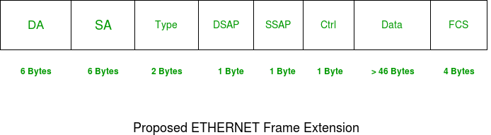
DA [Destination MAC Address] : 6 bytes
SA [Source MAC Address] : 6 bytes
Type [0x8870 (Ethertype)] : 2 bytes
DSAP [802.2 Destination Service Access Point] : 1 byte
SSAP [802.2 Source Service Access Point] : 1 byte
Ctrl [802.2 Control Field] : 1 byte
Data [Protocol Data] : > 46 bytes
FCS [Frame Checksum] : 4 bytes
Size of Ethernet Frame
Note – Size of frame of Ethernet IEEE 802.3 varies 64 bytes to 1518 bytes including data length (46 to 1500 bytes).
The following is a description of the Ethernet Frame Format described in the IEEE 802.3 Specification. The 802.3 Specification defines a 14 byte Data Link Header followed by a Logical Link Control Header that is defined by the 802.2 Specification.
The Diagram below analyses the Ethernet 802.3 Frame:
THE DATA LINK HEADER
Offset 0-5: The Destination Address
- The first six bytes of an Ethernet frame make up the Destination Address. The Destination Address specifies to which adapter the data frame is being sent. A Destination Address of all ones specifies a Broadcast Message that is read in by all receiving Ethernet adapters.
- The first three bytes of the Destination Address are assigned by the IEEE to the vendor of the adapter and are specific to the vendor.
- The Destination Address format is identical in all implementations of Ethernet.
Offset 6-11: The Source Address
- The next six bytes of an Ethernet frame make up the Source Address. The Source Address specifies from which adapter the message originated. Like the Destination Address, the first three bytes specify the vendor of the card.
- The Source Address format is identical in all implementations of Ethernet.
Offset 12-13: Length
- Bytes 13 and 14 of an Ethernet frame contain the length of the data in the frame frame, not including the preamble, 32 bit CRC, DLC addresses, or the Length field itself. An Ethernet frame can be no shorter than 64 bytes total length, and no longer than 1518 bytes total length.
THE 802.2 LOGICAL LINK CONTROL (LLC) HEADER
Following the Datalink Header is the Logical Link Control Header (LLC), which is described in the IEEE 802.2 Specification. The purpose of the LLC header is to provide a "hole in the ceiling" of the Datalink Layer. By specifying into which memory buffer the adapter places the data frame, the LLC header allows the upper layers to know where to find the data.
Offset 15: The Destination Service Access Point (DSAP)
- The Destination Service Access Point (DSAP), is a 1 byte field that simply acts as a pointer to a memory buffer in the receiving station. It tells the receiving network interface card in which buffer to put this information. This functionality is crucial in situations where users are running multiple protocol stacks, etc...
Offset 16: The Source Service Access Point (SSAP)
- The Source Service Access Point (SSAP) is analogous to the DSAP and specifies the Source of the sending process.
Offset 17: The Control Byte
- Following the SAPs is a one byte control field that specifies the type of LLC frame that this is.
USER DATA AND THE FRAME CHECK SEQUENCE (FCS)
Data: 43-1497 Bytes
- Following the 802.2 header are 43 to 1497 bytes of data, generally consisting of upper layer headers such as TCP/IP or IPX and then the actual user data.
FCS: Last 4 Bytes
- The last 4 bytes that the adapter reads in are the Frame Check Sequence or CRC. When the voltage on the wire returns to zero, the adapter checks the last 4 bytes it received against a checksum that it generates via a complex polynomial. If the calculated checksum does not match the checksum on the frame, the frame is discarded and never reaches the memory buffers in the station.
This completes our anaylsis of the Ethernet 802.3 frame.
LLC layer and mac layer
What is the difference between a MAC address and an LLC address
Actually data link layer has two sub layers one MAC and second LLC.
Mac address deals with the hardware address of Lan card which is hard coded and cant be changed , it is unique for every lan card.
second Logical link control (LLC) protocol data units (PDUs) contain addressing information. This addressing information consists of two fields; the Destination Service Access Point (DSAP) address field, and the Source Service Access Point (SSAP) address field. Each of these is an 8-bit field and each is made up of two components
LLC Layer (Logical Link Control): Data Link Layer Of OSI Model
LLC layer
if the MAC layer is responsible for the medium access then LLC layer is responsible for the logical link control for the data link layer. This is the property that makes LLC an important layer in the data link layer. In this article, we will take a deeper look into the LLC layer.
The data link layer is made up of two sublayers:
· LLC (Logical Link Control) Layer
Both of these two sublayers are responsible for different functions for the data link layer. Today, we are going to talk about the LLC layer in details.
LLC layer:
LLC layer is also known as the logical link control. For the data link layer, the LLC layer serves the purpose of providing end to end flow, error control, and multiplexing different protocols over the Mac layer of the data link layer.
For example:
Let’s assume that I am running Windows 10 and I want to do a video chat with my friend who is sitting across oceans in Germany. Now, here is what happens when we start the video chat:
· Multiplexing
So when I start video chatting, my application, that maybe Skype, starts generating video data packets. However, the data link layer has some restrictions like a packet size cannot be greater than a particular size, let’s say X bytes in total. That implies that the data packets have to be broken down into different chunks and those data packets have to be transmitted chunk by chunk.
Why so?
Let’s say you send data packets of longer sizes. Then, if that data packet is lost, you will have to send those packets once again. And the larger the size of the packet is, the larger bandwidth will be required to resend those data packets. That’s why an optimized frame size has been defined for the size of a data packet for data link layer.
So, now the data packets have been broken into frames and they will be sent chunk by chunk across the internet. So when my data link layer breaks the videos in chunks, it is smart enough to mark those frames with some cues. This allows my friend’s data link layer to exactly know the order of the frames so that it can re-arrange the frames back in order.
· Flow control
Another thing that LLC layer is responsible for is flow control. Let’s take a look at the flow control this way.
I am a not-so-rich person so I cannot afford a laptop and I am still working on old Windows PC with 256 Mb RAM. On the other hand, my girlfriend can afford a brand new laptop that was just launched in the market.
So when we video chat, because of the HD quality camera from her laptop, the video size I receive outsizes my video sent to her from my poor camera. Does that mean that we should run out of sync? No, that does not happen, right?
And that’s where exactly flow control comes into the picture. LLC layer makes sure that one fast computer does not overrun a slower one. For that purpose, the concept of ‘Ack’ acknowledgment has come into the picture. For every frame received or sent, I must send/receive an ack respectively to be in sync.
· Error control
LLC layer uses CRC (Cyclic Redundancy Check) to check frame errors at data link layer. This is more like providing a preview of a bigger picture to your friend that where he/ she is going wrong.
If you have any comments or thoughts related to it, feel free to ask and correct us.
MAC Layer Explained: The Top Sublayer Of Data Link Layer
MAC layer:
MAC layer is also known as Media Access Layer. As it is evident from the name itself that for the Data link layer, the MAC layer serves the purpose of managing the media access to different devices.
For example:
Let’s say there is a bus topology in which many computers are connected in a series. However, there is only one common media cable on which all the data has to be transferred.
We know the data is carried over on a cable in terms of electric signals. So, if more than one computer sends an electric signal at the same time, there will be a signal collision which will turn into the data packets loss on the wire. And that’s where MAC layer comes into the picture.
Channel access control Mechanisms applied by Mac layer:
Different kind of channel access control mechanisms are applied by the MAC layer for media access and here are some of the popular channel access control mechanisms:
· Token passing
· CSMA/ CD
· CSMA/ CA
· Slotting mechanism etc.
Token Passing:
A token is passed among the data competitors for a limited amount of time to release the data on the common channel. There are many variants of this mechanisms. Here are some:
· For the quality of service, the token is passed for longer times to a particular node
· A node with more data gets the token for the longer time.
CSMA/ CD:
CSMA/ CD stand for Carrier sense multiple access with collision detection (CSMA/CD). It’s a media access control method used most notably in local area networking using early Ethernet technology.
When two nodes send data packet at the same time, then a collision happens. When a collision happens, a jam signal is sent along the wire which tells all the nodes that there has been a collision in the wire. All the nodes stop sending data for a while, for a random time interval before resuming the sending process again.
CSMA/ CA:
CSMA/ CA stand for Carrier sense multiple access with collision Avoidance (CSMA/CA).
CSMA/ CA came into the picture because the problem with CSMA/ CD was that it detected collision after it happened. That means the damage was already done and the mechanism was looking for the recovery after the damage.
However, in the case of CSMA/ CA, the data packet will only be sent if the media is free from packets. When a node senses that there is some transmission going on the media channel then it will wait for a random time before sensing the media channel once again.
Slots:
Slotting mechanism mostly came from the Aloha system. However, the Aloha system has also seen a lot of modifications.
Like in pure aloha, all the nodes sent packets at any time but this mechanism was improved in slotted aloha where all the nodes could send packets only at the beginning, at one slot.
UDP EXPLAINED
Some common protocols which use UDP are: DNS, TFTP, ARP, RARP and SNMP.
When people refer to "TCP/IP" remember that they are talking about a suite of protocols, and not just one (as most people think). TCP/IP is NOT one protocol. Please see the Protocols section for more information.
The User Datagram Protocol (UDP) is defined by IETF RFC768
1) User Datagram Protocol (UDP) is a connectionless protocol, which means UDP is not a reliable protocol when compared with Transmission Control Protocol (TCP).
2) User Datagram Protocol (UDP) is capable of performing fundamental error checking. The UDP header includes a checksum field that the destination device can use to check the integrity of the data.
3) User Datagram Protocol (UDP) does not provide sequencing of data. Therefore, the data may arrive at the destination device in a different order from which it was sent. This may happen in large networks, such as the Internet, where the Datagrams might take different paths to the destination and experience delays in different routers. In a LAN, sequencing is not going to create problems. Applications that require sequencing must code their own sequencing mechanism as part of the application.
User Datagram Protocol (UDP) Header
Source Port Number: The first 16 bits of the UDP header contain the port number of the application sending the data.
Destination Port Number: The next 16 bits contain the port number of the application that receives this data.
Length: The next 16 bits identify how long the datagram is in bits.
Checksum: The last 16 bits of the UDP header are reserved for the checksum value. Checksum is used as an error-detection mechanism. The source machine runs a mathematical algorithm on the datagram. The destination, or recipient, machine runs the same mathematical algorithm on the datagram. If the both values match we can assume that the datagram wasn't damaged while its journey.
The checksum field includes a 12-byte 'pseudo header' that includes the source and destination IP addresses, the 8-bit reserved field containing 0, the 8-bit protocol ID and the 16-bit UDP length field. The pseudo header is useful to check that the IP datagram arrived at the correct station.
Important protocols which use UDP as the Transport Layer protocol are Trivial File Transfer Protocol (TFTP), Domain Name System (DNS), Remote Procedure Call (RPC) used by the Network File System (NFS), Simple Network Management Protocol (SNMP) and Lightweight Directory Access Protocol (LDAP).
UDP - USER DATAGRAM PROTOCOL
The second protocol used at the Transport layer is UDP. Application developers can use UDP in place of TCP. UDP is the scaled-down economy model and is considered a thin protocol. Like a thin person in a car, a thin protocol doesn't take up a lot of room - or in this case, much bandwidth on a network.
protocol used at the Transport layer is UDP. Application developers can use UDP in place of TCP. UDP is the scaled-down economy model and is considered a thin protocol. Like a thin person in a car, a thin protocol doesn't take up a lot of room - or in this case, much bandwidth on a network.
UDP as mentioned dosen't offer all the bells and whistles of TCP, but it does a fabulous job of transporting information that doesn't require reliable delivery and it does so using far fewer network resources.
Unreliable Transport
UDP is considered to be an unreliable transport protocol. When UDP sends segments over a network, it just sends them and forgets about them. It doesn't follow through, check on them, or even allow for an acknowledgment of safe arrival, in other words .... complete abandonment! This does not mean that UDP is ineffective, only that it doesn't handle issues of reliability.
The picture below shows us the UDP header within a data packet. This is to show you the different fields a UDP header contains:
CONNECTION-LESS ORIENTED
For those who read our TCP section, you would know it is a connection oriented protocol, but UDP isn't. This is because UDP doesn't create a virtual circuit (establish a connection before data transfer), nor does it contact the destination before delivering information to it. No 3-way handshake or anything like that here!
Since UDP assumes that the application will use its own reliability method, it doesn't use any, which obviously makes things transfer faster.
LESS OVERHEAD
The very low overhead, compared to TCP, is a result of the lack of windowing or acknowledgments. This certainly speeds things up but you get an unreliable (in comparison to TCP) service. There really isn't much more to write about UDP so I'll finish here.
TRIVIAL FILE TRANSPORT PROTOCOL - TFTP
Rating 3.71 (7 Votes)
%2C...)
TFTP is a file transport protocol and its name suggests it's something close to the FTP protocol (File Transfer Protocol), which is true .. to a degree. TFTP isn't very popular because it's not really used on the Internet because of its limitations which we'll explore next.
THE PROTOCOL
TFTP's main difference from FTP is the transport protocol it uses and the lack of any authentication mechanisim. Where FTP uses the robust TCP protocol to establish connections and complete the file transfers, TFTP uses the UDP protocol which is unsecure and has no error checking built in to it (unless they have implemented some type of error checking in the program you are using to transfer files), this also explains why you are more likely to find TFTP in a LAN, rather than a WAN (Wide Area Network) or on the Internet.
The major limitations with TFTP are authentication and directory visibility, meaning you don't get to see the files and directories available at the TFTP server.
As mentioned, TFTP uses UDP as a transport, as opposed to TCP which FTP uses, and works on port 69, you can clearly see that in the cool 3D diagram on the left.
Port 69 is the default port for TFTP, but if you like, you can modify the settings on your TFTP server so it runs on a different port.
Now, to make things a bit clearer I have included a screen shot of my workstation tftp'ing into a TFTP server which I have setup in my little network.
You can see my workstation (192.168.0.100) contacting the TFTP server (192.168.0.1) on port 69(destination port). In this first packet, my workstation is contacting the server and requesting the file I entered before I connected to the server. Click here for the full picture.
Because you don't get a listing of the files and directories, you must know which file you want to download ! In the response I received (2nd packet) the server gets straight into business and starts sending the file. No authentication whatsoever !
Note: The workstation usally won't send back any acknowlegement (because UDP, which is the transport protocol, by nature, never sends acknowledgements), but the software developers can incorporate such a feature by forcing the workstation to send a small packet which the TFTP server is able to pickup as an acknowledgement of the previous data packet it sent to the workstation.
In the example I provide, you can see my workstation sending small packets to the server after it receives one packet from it. These small acknowledgements have been added by the software company who created the program I was using for this example.
Below is a screen shot of the program I used to TFTP (TFTP Client) to the server:
Notice how I entered the file I wanted to downloaded (server.exe), and selected the name which the file will be saved as on my local computer (Local File). If I didn't provide the Remote File name, I would simply get an error poping up at the server side, complaing that no such file exists. You can also send files using TFTP, as it's not just for downloading :)
·
No comments:
Post a Comment